Model EZGas Pro gas burner — Instruction manual
MNEZGas 011917
– 22 –
Where appliance instructions differ from this manual, follow the appliance instructions.
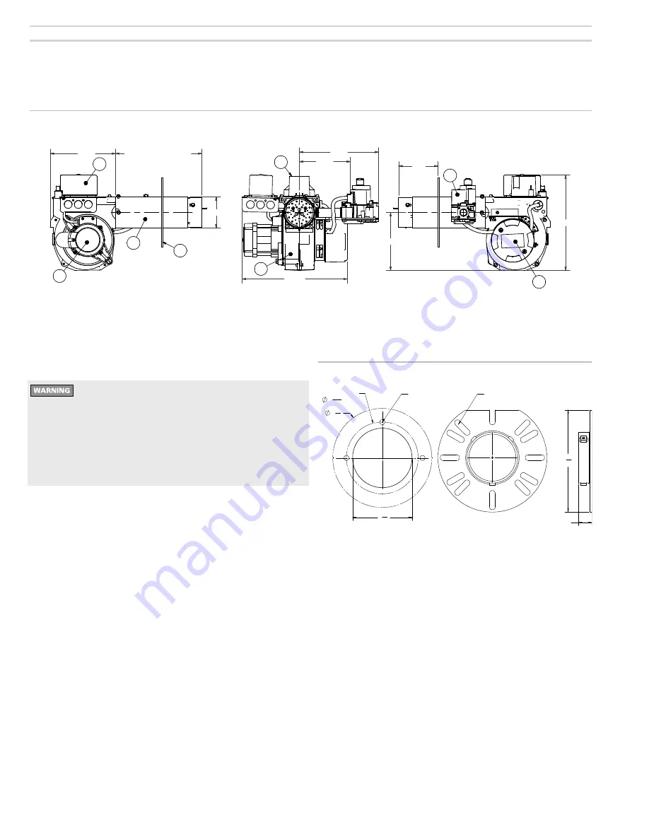
8. Dimensions and mounting information
Figure 9
Dimensional data
Mounting burner to appliance
The universal flange can be used as supplied for
firing chambers with negative overfire pressure.
For pressurized firing, the entire space where
the airtube meets the flange must be sealed
with a high temperature silicone sealant rated
for at least 400
°
F. Failure to comply could result
in severe personal injury, death or substantial
property damage.
Prepare the burner opening on the front of the appliance as
shown in Figure 10 if not already supplied. See page 7 to
determine the location of the flange on the burner air tube.
Tighten the flange locking screws firmly.
Figure 10
Universal mounting flange
1- Carlin 60200FR microprocessor control
2- Air tube
3- Flange (selected to meet appliance requirement)
4- Carlin 41800 solid state ignitor
5- Combination gas valve
6- Carlin PSC motor
7- Cast aluminum blower housing
8- Transformer and Air flow proving switch
QUALITY CHARACTERISTICS
CRITICAL
MAJOR
A
MAJOR
B
MINOR
NO
SYMBOL
CRITICAL
STATISTICAL
SEE QAS 1000 FOR VENDORS QUALITY
ASSURANCE REQUIREMENTS
TOLERANCE UNLESS OTHERWISE SHOWN
FRACTIONAL
`
1/64 ANGLE
`
1/2
~
DEC. .XX `
.01 .XXX
`
.005
THIS DOCUMENT MAY NOT BE
REPRODUCED WITHOUT WRITTEN
PERMISSION FROM CARLIN
COMBUSTION TECHNOLOGY, INC.
REMOVE BURR AND FLASH FOR
PROPER OPERATION AND GOOD
APPEARANCE
THIRD ANGLE PROJECTION
DO NOT SCALE DRAWING
INTERPRET ALL DIMENSIONS
PER ANSI Y14.5 1994
CARLINCOMBUSTIONTECHNOLOGY,INC.
EASTLONGMEADOW,MAU.S.A.
PART
NUMBER
MAT'L
NUMBER
PART
DESC.
MAT'L
DESC.
ITEM
CLASS
ITEM
CLASS
ECN #
REV SH
OF
DRAWING
NUMBER
DRAWN
DATE
SCALE
EZ
GAS_RevA_FlippedElectrode_Dims
wmisiaszek
9/4/2013
ECN
BSIZE
ALL LINEAR DIMENSIONS
ARE IN INCHES
REVISION HISTORY
REV
DESCRIPTION
ECN
BY
DATE
.
Released to Production
ECN
MPC
5/4/2009
3 1/2"
7 3/8"
Air tube length
(as needed for apliance)
5 7/8"
9 1/4"
11 3/4"
6 3/4"
10 3/4"
UTL
6
1
2
3
4
7
5
8


