


INSTALLATION
Before proceeding, make sure trigger lock is engaged.
NOTE
1. Connect your high-pressure fluid hose to the gun fluid
inlet and tighten securely.
2. Connect your air hose to the gun air connection and
tighten securely.
3. Slowly increase air to the pump to obtain a fluid pressure
at the gun’s lower end of the pressure range. A typical
starting fluid pressure is 17 bar [250 psi]. Actual starting
pressure points may be higher or lower and be dependent
on the type of pump used, the type of material sprayed,
and the spray gun itself.
4. Using the control knob of the gun air regulator at the air
control, set the gun shaping air pressure at 0 bar [0 psi].
5. To test the spraying pattern, spray a sample piece of wood
or cardboard with a fast pass about 30cm [1 ft] away
from the surface. The results of the test will allow you to
determine the uniformity of the particle size and spraying
pattern.
6. If the spraying pattern develops tails or is not uniform,
gradually increase the air pressure as necessary to
develop a uniform spraying pattern. 1 bar [14 psi] is the
maximum inlet air pressure for HVLP air caps, or use 1.4-
2.8 bar [20-40 psi] inlet air pressure for LVMP air caps.
7. If the pattern is still unacceptable, you may gradually
increase the fluid pump air pressure in 3 bar [50 psi]
increments using the fluid pump air regulator control
knob. Repeat step 6, as needed.
8. Once the quality of spray is acceptable, begin spraying.
If the spraying rate is too slow to keep up with the
production line speed, or if the quantity of material
sprayed is inadequate for acceptable coverage, repeat
step 7, until desired pattern and material quantity is
achieved. If the maximum fluid pressure is reached before
the required material coverage and spraying speed are
achieved, you may need to switch to a different fluid tip.
FLUID TIP SELECTION
Factors to consider in selecting a fluid tip for an air-assist
airless spray gun include:
• The size of the parts being sprayed.
• The production line speed
• The material flow rate and film thickness.
• The viscosity of the material applied
• The type of material applied.
• The quality of atomization of the coating required.
The selection of a fluid tip necessary to perform a specific
spraying job is best determined through a combination of
experimentation and expert advice from your material and
equipment suppliers.
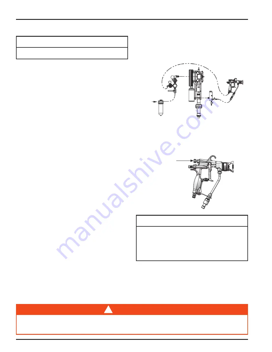
Air Supply
Oil & Water
Extractor
MX Pump
Fluid
Filter
Air
Control
Trophy AA
Spray Gun
SPRAY PATTERN ADJUSTMENT
• Turn the spreader valve knob indicated below
counterclockwise to decrease the pattern size;
clockwise to increase pattern size.
Spray pattern adjustment
control knob
For HVLP spray, spray pattern adjustment feature requires
1 bar [14 psi] maximum of air inlet pressure.
For LVMP spray, spray pattern adjustment requires
approximately 1.4-2.8 bar [20-40 psi] of air inlet pressure.
Higher fluid pressures will require a higher air inlet pressure
to accommodate pattern adjustment.
NOTE
FLUID HOSES
Air-assist airless spray guns operate at fluid pressures higher
than operating pressures of air spray guns. As a result, when
operating an air-assist airless spray gun, it is critical to select
the appropriate fluid hose that is rated for the pressure range
at which the airless gun is operated.
The spray gun must be earthed to dissipate any electrostatic charges which may be created by fluid or air flows.
This can be achieved through the spray gun mounting, or conductive air/fluid hoses. Electrical bond from the spray gun to earth
should be checked and a resistance of less than 10
6
Ohms is required.
!
WARNING
EN
77-3130-R4 (5/2019)
4 / 16
www.carlisleft.com


