


TROUBLESHOOTING SPRAY PERFORMANCE
Always engage trigger lock and relieve fluid pressure.
!
CAUTION
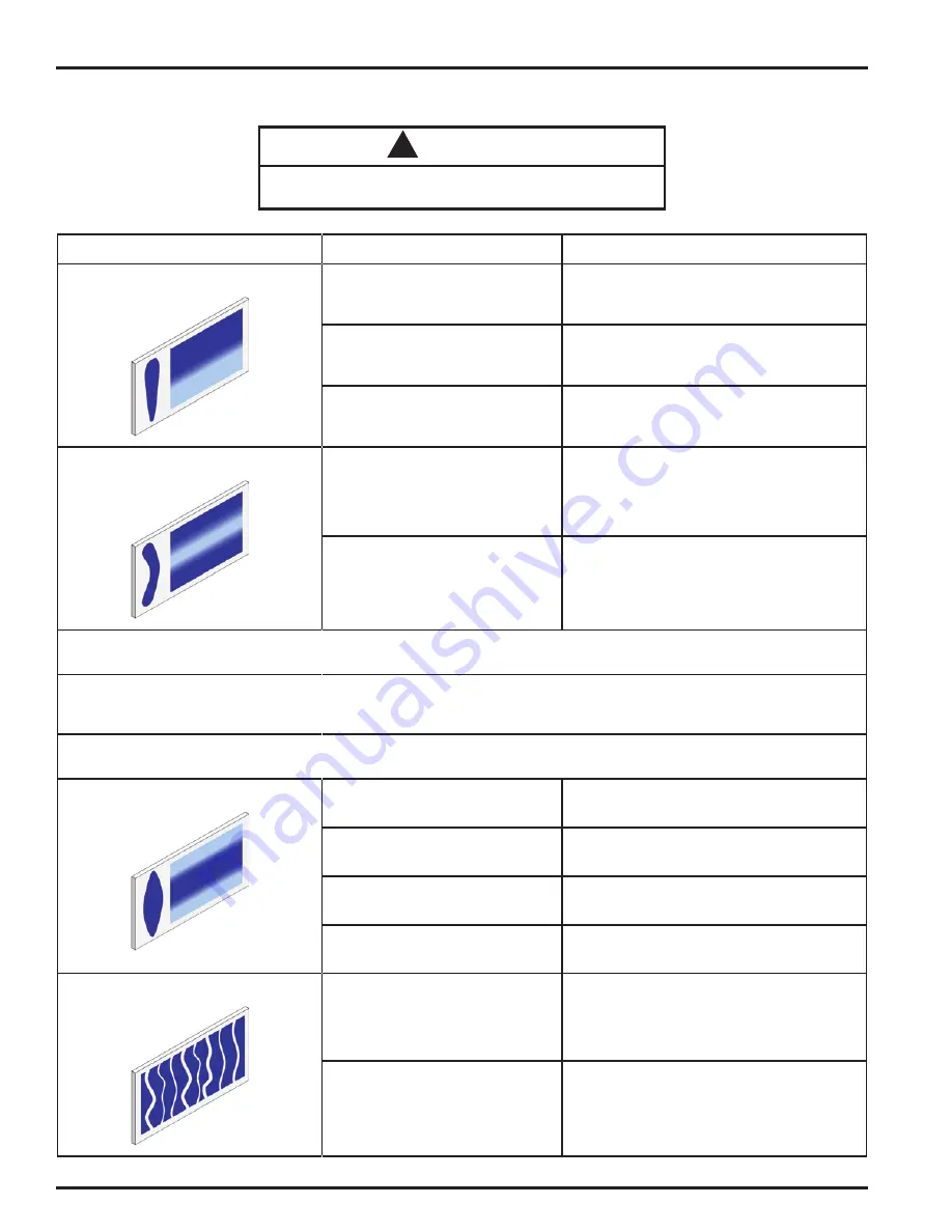
PROBLEM
CAUSE
CORRECTION
Heavy top or bottom pattern.
Material build-up on air cap, plugged
horn holes, center holes or jets.
Soak cap or tip in suitable solvent and thoroughly
clean.
Material build-up on fluid tip exterior or
partially plugged fluid tip.
Replace fluid tip or air cap if necessary.
Fluid tip or cap dirty or damaged.
Replace fluid tip or air cap if necessary.
Heavy right or left side pattern.
Left or right side horn holes plugged.
Soak cap or tip in suitable solvent and thoroughly
clean.
Dirt or damage on left or right side of
fluid tip exterior.
Replace fluid tip or air cap if necessary.
Remedies for the top-heavy, bottom-heavy, right-heavy and left-heavy patterns.
Determine if the obstruction is on the air cap or the fluid tip. Do this by making a test spray pattern. Then, rotate the air cap and tip one-half
turn and spray another pattern. If the defect is inverted, obstruction is on the air cap. Clean the air cap as previously instructed. Also check for
dried paint just inside the cap center hole opening, remove by washing with solvent.
If the defect is not inverted, it is on the fluid tip. Clean tip. If problem persists, renew tip.
Heavy center pattern.
Pattern adjustment valve set too low.
Turn out counter clockwise to achieve correct
pattern.
Too much material.
Reduce fluid pressure.
Material too thick.
Thin to correct consistency.
Atomizing air pressure too low.
Increase air pressure.
Intermittent or 'fluttering' spray fan.
Fluid tip not seated correctly in gun
head.
Remove fluid tip, clean components, check
cone seating on tip and gun for damage or
contamination.
Partially obstructed fluid passage or
hose.
Clean or replace.
EN
77-3130-R4 (5/2019)
6 / 16
www.carlisleft.com


