ATTENTION!
READ BEFORE ATTACHING THE AIR HOSE
HVLP AIR SUPPLY REQUIREMENTS
FULL SIZE GUN:
30 PSI inlet pressure provides 10 PSI at the air cap. Consumes 13 CFM.
TOUCHUP GUN:
30 PSI inlet pressure provides 10 PSI at the air cap. Consumes 8 CFM.
NOTE: USE 5/16" OR LARGER I.D. AIR HOSES
4. If desired, attach air adjust-
ing valve with gauge and/
or quick disconnect to air
inlet, then attach hose.
5. Spray test and adjust air
pressure, fan size, and
fluid flow as required.
R e c o m m e n d e d s p r a y
distance is 6-8 inches.
SET-UP AND ADJUSTMENT INSTRUCTIONS
1. Attach cup to gun and
flush solvent through gun
to remove oils.
2. Tighten packing nut—see
instructions.
3. Fully open fan and fluid
needle controls (turn
counter-clockwise).
Before using this spray gun,
the packing nut should be
adjusted as follows:
1. Tighten packing nut until
fluid needle starts to bind
in the packing.
2. Loosen packing nut just
enough so the fluid needle
moves freely.
PACKING ADJUSTMENT INSTRUCTIONS
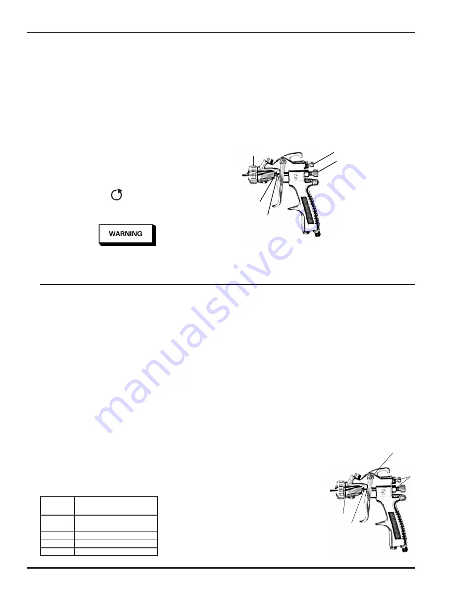
AIR CAP
PACKING
NUT
FLUID NEEDLE
FAN CONTROL
FLUID NEEDLE CONTROL
The packing nut is intentionally left loose so the PTFE packing
does not take a "set" before the spray gun is used. This allows
full utilization of the packing.
A failure resulting in injury or damage may be caused by pressure
beyond top of scale, excessive vibration or pressure pulsation,
excessive instrument temperature, corrosion of the pressure con-
taining parts or other misuse of the air adjusting valve with gauge.
A
C
B
D
Spray a test area. Turn the fluid needle
adjusting knob counterclockwise until a
full coat is obtained.
If the finish is too sandy and dry, the
material flow may be too low for the
atomization air pressure being used.
Turn the fluid needle adjusting knob
counterclockwise to increase fluid flow.
If the finish sags, there is too much mate-
rial flowing for the atomization air pressure
being used. Turn the fluid needle adjusting
knob clockwise to decrease fluid flow.
Pattern width can be altered by turn-
ing spreader adjustment valve, either
clockwise to decrease the width or coun-
terclockwise to increase the width.
Adjust inlet air pressure to provide a uni-
form dispersion of atomized paint through-
out the pattern. Keep air pressure as low
as possible to minimize bounce-back and
overspray. Excessive pressure will result in
split spray patterns. Inadequate pressures
will cause heavy centered patterns and
poor atomization.
CLEANING
For routine cleaning, it is not necessary
to remove cup from gun. Remove lid and
properly dispose of any excess paint. Pour
in a small amount of clean solvent. The
amount will vary with different coatings and
solvents. Reinstall lid. Shake cup to wash
down the inside surfaces. Pull trigger to
allow some solvent to be flushed through
gun. Remove lid and pour out dirty solvent.
Add a small amount of clean solvent and
repeat procedure. Wipe exterior of lid with
a clean cloth and clean solvent.
If a paint filter was used in the bottom of
the cup outlet, it should be removed and
cleaned at this time.
To clean air cap and fluid tip, brush exte-
rior with a stiff bristle brush. If necessary
to clean cap holes, use a broom straw or
toothpick if possible. If a wire or hard instru-
ment is used, extreme care must be used to
prevent scratching or burring of the holes
which will cause a distorted spray pattern.
To clean fluid passages, remove excess
material at source, then flush with a suit-
able solvent. Wipe gun exterior with a
solvent dampened cloth. Never completely
immerse in solvent as this is detrimental
to the lubricants and packings.
PREVENTIVE MAINTENANCE
Spray Gun Lubrication
Apply a drop of spray gun lube at trigger
bearing stud and the stem of the air valve.
The shank of the fluid needle where it enters
the packing nut should also be oiled. The
fluid needle packing should be kept soft
and pliable by periodic lubrication. Make
sure the baffle and retaining ring threads
are clean and free of foreign matter. Before
assembling retaining ring to baffle, clean
the threads thoroughly, then add two drops
of spray gun lube to threads. The fluid
needle spring and air valve spring should
be coated with a very light grease, making
sure that any excess grease will not clog
the air passages. For best results, lubricate
the points indicated, daily.
A. Trigger Points
B. Packing
C. Adjusting Valve
D. Baffle/Air Cap Threads
Fluid Tip
Size (mm) Applications
1.0
General purpose, light to medium
viscosity material.
1.3
Top coats.
1.5
Top coats and primer sealers.
1.8 Primers.
EN
SB-2-610-R1 (4/2018)
2 / 3
www.carlisleft.com


