18
© Carlo Gavazzi A/S
A SIN code is built up with 3 groups each consisting of 3 numbers� An example could be: SIN
019�113�001� During configuration, the SIN codes for the L1 and L2 Carpark Master Channel Gener-
ators respectively needs to be entered� This allows the Carpark Counter module to determine which
module shall be used for bus L1 and which module to be used for bus L2�
The LEDs on the front indicate the status of the Carpark Master Channel Generator�
All LEDs will turn on for a few seconds during power ON� Depending on what is connected to the
module, at least the BUS LED and ON LED will be ON�
BUS LED indicates internal bus running (amber)� The internal bus is running via the 6 pin intercon-
nection (see remark on the picture below)� This LED will be ON 20 seconds after “Power ON”
LED indicates 3-wire Dupline bus L1 is running (amber)�
ON LED indicates power on the module (green)� This LED will be ON 20 seconds after “Power on”�
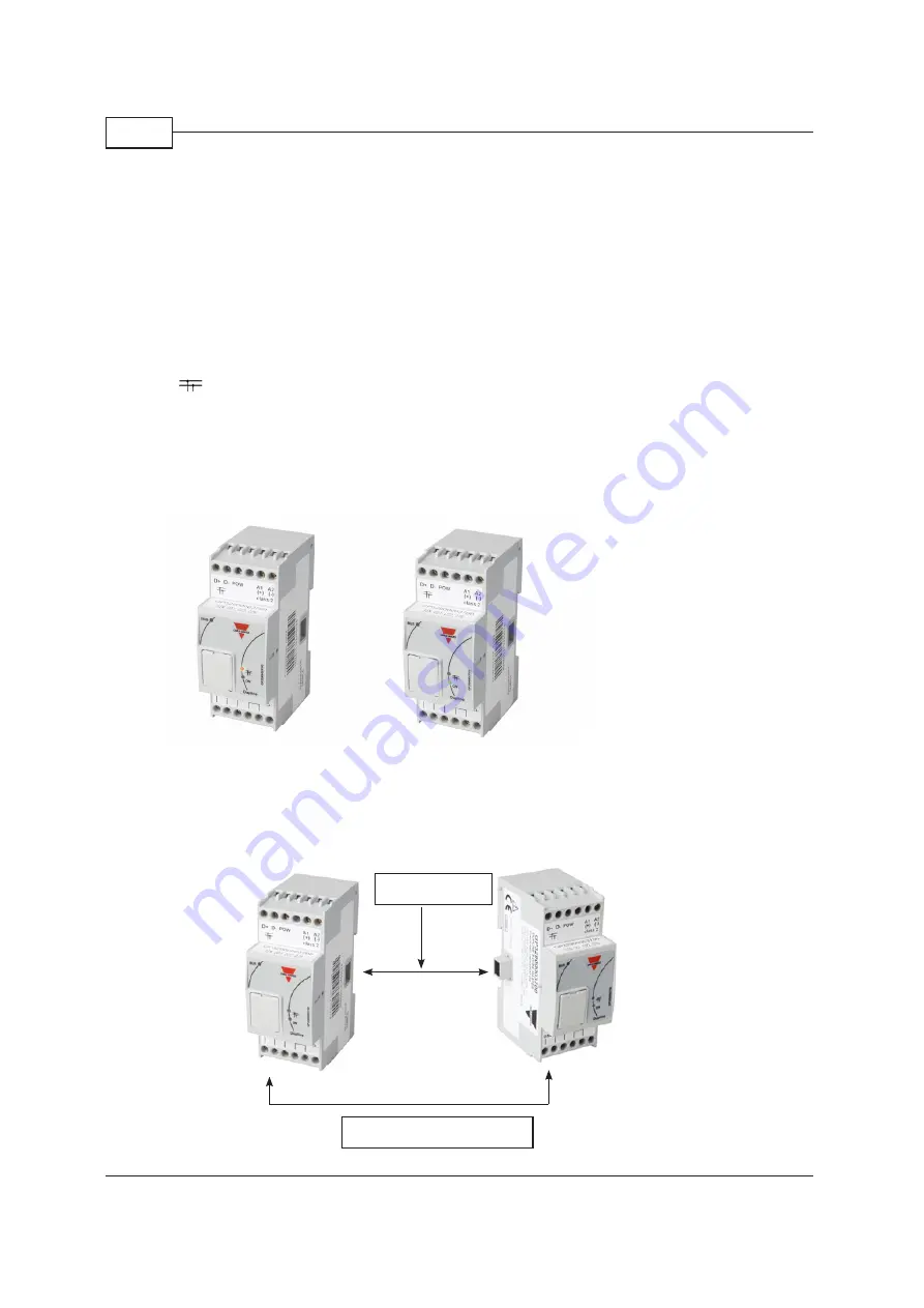
HS BUS for all module types
The internal HS bus linking the 3 modules together via the connectors on the sides can also be
implemented as an RS485 connection if desired� This allows the 3 modules to be installed in different
panels�
6 pin connector
External HS BUS connection
Fig. 9 : GP32900003700 - LEDs
Fig. 10 : Internal or external HS Bus connection


