46
© Carlo Gavazzi A/S
The sensor sends out a 30 kHz ultrasonic signal and it is important that the receiver inside the sensor
is able to detect the returning signal without problems� If the angle is problematic or the surface has a
poor quality, the signal can be interrupted resulting in the sensor's flashing red�
The sensor must be mounted in the middle of the parking space to ensure a perfect and reliable signal�
Fig. 39: Mounting in a parking space
The sensor can be programmed as “Normal sensor” or “Lane sensor”� “Lane sensor” is used to mon-
itor cars that enter the main entrance or areas in the Parking Guidance System Centre� It is necessary
to mount the “Lane sensor” directly over the lane� All Parking Guidance System sensors, “Normal
sensor” and “Lane sensor” must be mounted following the same rules�
Programming the Sensor
By using the programming tool GP7380 0080 the installer can program and test the sensors�
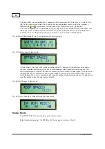
Fig. 40: Sensor and programmer GP7380 0080
The sensors do not need power during programming� The power is supplied from the programmer
GP7380 0080� This means that it is possible to program not only sensors that are already installed but
also sensors not yet installed� The installer can pre-program sensors before installation and write the
address on the back of the sensor with a permanent pen� This will be a time saving advantage during
installation�
When the programmer is connected to the sensor, press the “Read /on” button�
Fig. 41
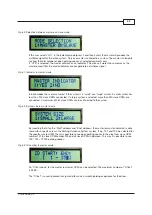
Normal mode
: The standard sensor mode - normal mode - detects the presence of a car in the park-
ing space, turns on the red LED and sends out a signal on the L1 bus� If the parking space is empty,
the LED will change to green and send out a signal on the L1 bus�
When the Configuration unit is connected to a 3-colour sensor/LED indicator, a new option is availa-
ble�
If the Configuration unit is connected to a 3-colour sensor, both LED CH1 and LED CH2 must be
assigned to a unique Dupline address�
If the Configuration unit is connected to a 3-colour LED indicator, it is possible to deselect LED CH2
by pressing tactile key “X”� LED CH1 does not need to be assigned to a unique address but can be
assigned to the same address as the “Status” address�
Fig. 42
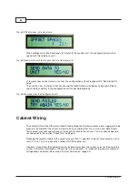
Lane mode
: The sensor is placed on the ceiling above the lane and detects the car before it enters
the parking area� The Parking Guidance System will reduce the total number of open spaces because
of the moving car and show the reduced number on the display� This is to prevent too many moving
cars in a specific Parking Guidance System area�
It is possible to see or change the status and calibration address for the connected sensor�
Fig. 43
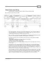
Select the address by pressing the numeric key on the programming unit GP7380 0080�
Program the Parking Guidance System space sensors starting from A1 and forward�
Roof
Floor
Roof
Floor
Roof
Wall
Floor
Roof
Wall
Floor


