54
© Carlo Gavazzi A/S
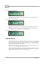
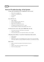
Fig. 64: Offset spaces in master mode
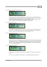
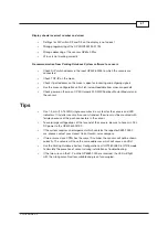
When settings are finished and ready to transfer to the monitor unit, the configuration unit will re-
spond with “Send data to unit”�
Fig. 65. Send data to unit (both sensor and master/slave unit)
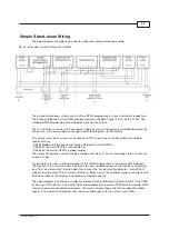
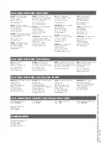
If, for some reason, the transmission fails, the configuration unit will respond with “Send failed Try
again”�
The user then has to find out what has caused the failed transmission before trying again� Please
check cable or battery in the configuration unit for possible problems�
Fig. 66. Message from the Configuration unit
Cabinet Wiring
The cabinet(s) for all the DIN rail mounted Parking Guidance System modules is(are) suggested to be
placed in the middle of the system in order to have a uniform load� This is also a cost benefit (only
few cabinets are used) and will reduce the length of cable to the sensors� This has already been dis-
cussed earlier in the section “Phase two” on page 6�
Reducing the length of cable to the sensors means that it is possible to mount more sensors on the
same L1 bus� This can reduce the number of CPM modules etc�
However, if requested, the cabinet(s) can be installed away from the system or just at the end of the
system� If the rules mentioned in “Phase two” are not obeyed, it is important to perform a load and
voltage drop calculation� See section “System Calculation” (page 55)�


