9
© Carlo Gavazzi A/S
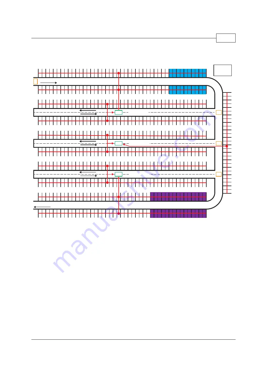
Fig. 2: Example of a Parking Level with Phase 2 Considerations:
A, B, C and D are placement of displays
Segments 1 to Segment 5 are based on the lanes and the open spaces on each side of the lanes�
44 spaces on each side of the lane (88 in total) and in segment 6 are only 29 spaces�
Handicap spaces (blue spaces) are placed close to the elevator�
Cabinets C1, C2 and C3 are logically placed in the middle of the wiring between the sensors�
VIP area� 3-colour sensor used with Carpark software�
Phase 3: Design One Segment (…and Build From There)
•
As a rule-of-thumb, there is a maximum of 70 sensors and 200 m (660 feet) of wire in a
branch� The wire should be a 14-16AWG and unshielded� There should be a maximum of
120 sensors per segment� If the branch has less than 65 sensors and the wire length is
longer than 200 m(660 feet) please refer to the voltage drop calculation detailed on page 55�
•
If the 3-colour sensor /led indicator solution is used, be aware that only 40 sensors can be
mounted on the same segment� Each sensor/led indicator occupy max� 3 Dupline address-
es: 120/3 = 40 sensors�
Entrance
Exit
Segment #1
Segment #2
Segment #3
Segment #4
Segment #5
Segment #6
A
B
C
D
Handicap
C1
C2
C3
Elevator


