4
Specifications are subject to change without notice (09.06.2021)
DWB03, PWB03
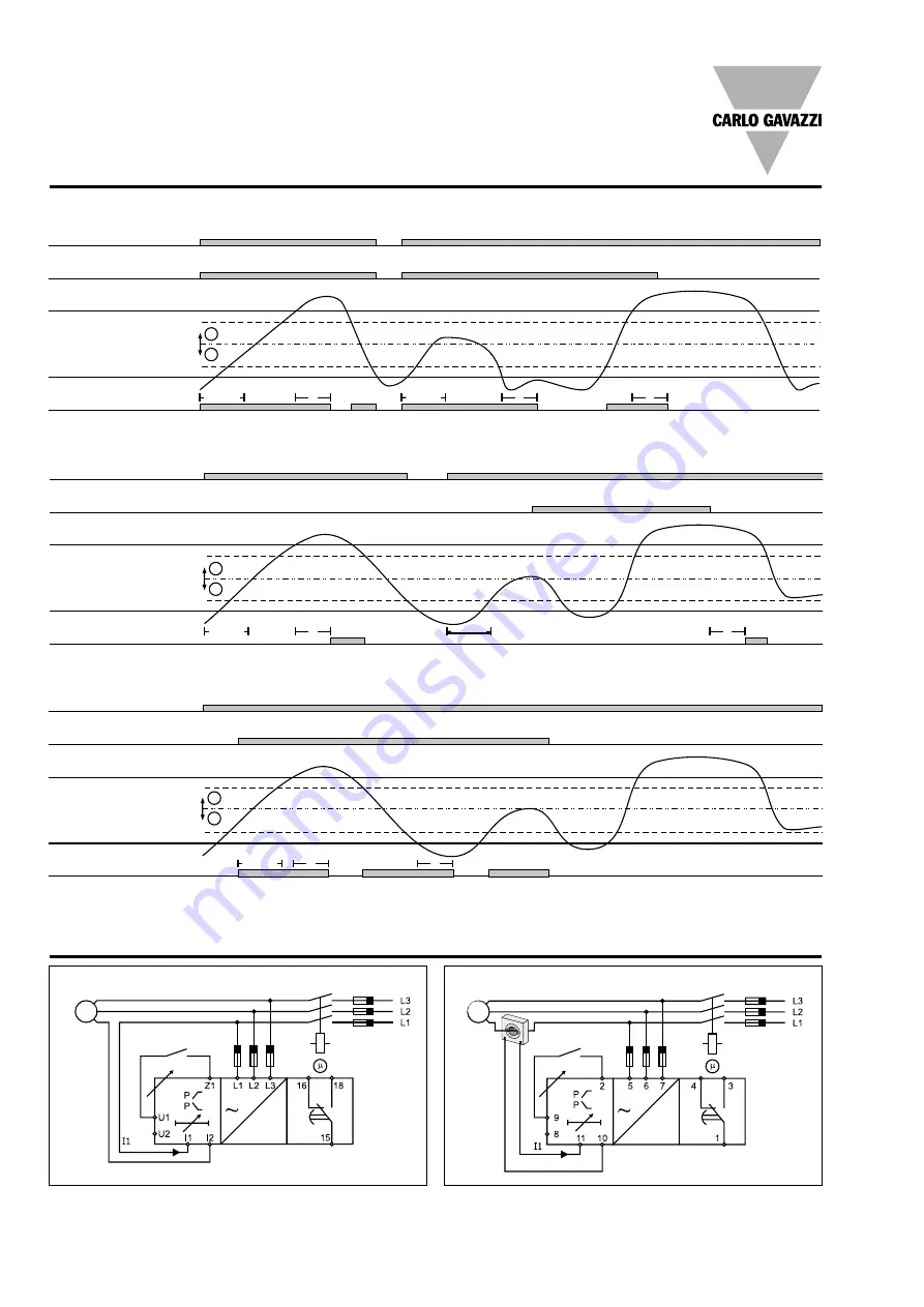
Operation Diagrams
T
T
T
M
G
P=0 W
Latch function - NE relay
T
T
M
G
P=0 W
Inhibit function - ND relay
T
T
M
G
P=0 W
Start and stop function - NE relay
Power supply
Latch contact
(Closed = latch not active)
Upper level
Hysteresis
Hysteresis
Active power
Power
ON
Power
ON
Power
ON
Power ON
Power
ON
Lower level
Relay ON
Power supply
Start/Stop contact
(Closed = Start; Open = Stop)
Upper level
Hysteresis
Hysteresis
Active power
Lower level
Relay ON
Power supply
Inhibit contact
(Closed = inhibit active)
Upper level
Hysteresis
Hysteresis
Active power
Lower level
Relay ON
Wiring Diagrams
DWB03 - Direct connection
PWB03 - Direct connection
Latch/Inhibit
Contact
Latch/Inhibit
Contact
M/G
M/G


