28
NRG User Manual | © 2020 | CARLO GAVAZZI LTD.
V1.0 | NRG EtherCAT User Manual | © 2022 | CARLO GAVAZZI LTD.
EN
7.
Alarms and Diagnostics
The NRG bus chain is equipped with on-board diagnostics to facilitate troubleshooting. The status of each component
can be identified via the status LEDs on the façade of the product as well as via the communication system.
The errors identified by the NRG controller indicate any identified issues relating to the status of the NRG internal bus.
On the other hand, the alarms on the NRG solid state relay indicate any alarms relating to the SSR or the process.
7.1
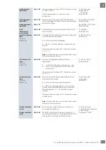
LED indications – NRG Controller
ON
Green
ON:
US is present at terminals Us+ Us-
OFF:
US is not present at terminals Us+ Us-
LINK /ACT
Green
ON:
The NRG controller is linked to Ethernet
OFF:
The NRG controller has no link to Ethernet
BUS
Yellow
ON:
Transmission of messages from NRG Controller to RG..Ns
OFF:
Internal bus is idle
RUN
Green
ON:
Operational
: The device is in OPERATIONAL state
Flickering:
Pre-Operational
: The device is in PRE-OPERATIONAL state
Single Flash:
Safe-Operational
: The device is in SAFE-OPERATIONAL state
OFF:
INIT
: The device is in INIT state
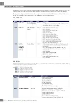
ERR
Red
Flickering:
Invalid configuration
: General Configuration error
Possible reason: State change commanded by master is
impossible due to register or object settings.
Double Flash:
Application watchdog timeout
: An application watchdog timeout
has occurred. Possible reason: Sync Manager Watchdog timeout.
Single Flash:
Local error
: Slave device application has changed the EtherCAT
state autonomously.
Possible reason 1: A host watchdog timeout has occurred.
Possible reason 2: Synchronization error, device enters Safe-
Operational automatically.
OFF:
No error
: The EtherCAT communication of the device is in working
condition.
Alarm
Red
2 Flashes:
Configuration error
(Device limit error, Device conflict error, Device unconfigured error,
Device position error)
4 Flash
Supply error
8 Flashes
Communication error
9 Flashes
Internal error
10 Flashes
Termination error
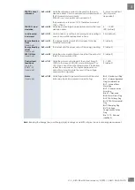
7.2
LED indications – RG..N
LOAD
Green
ON:
SSR output is ON
OFF:
SSR output is OFF
BUS
Yellow
ON:
Communication ongoing between NRG controller and RG..Ns
OFF:
Communication between NRG controller and RG..Ns is idl
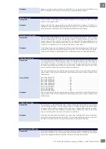
Alarm
Red
100% ON: SSR over-temperature
1 Flash
Load deviation
2 Flashes
Mains loss
3 Flashes
Load loss / SSR open circuit
4 Flashes
SSR short circuit
5 Flashes
Frequency out of range
6 Flashes
Current out of range
7 Flashes
Voltage out of range
8 Flashes
Communication error (BUS)
9 Flashes
Internal error


