background image

23

IT IS IMPORTANT that the instrument is switched
off when you plug-in or disconnect the modules.

For  SAFETY reasons, in the 20 (90)A version,

the tightening torque value of the current terminals must
be within 2Nm and 6Nm.

 List of the variables

Variables that can be retransmitted by means of an analogue
output or controlled by means of an alarm output.

d

m

d

W

d

n

a

m

e

d

r

e

w

o

p

e

v

i

t

c

A

d

m

d

A

V

d

n

a

m

e

d

r

e

w

o

p

t

n

e

r

a

p

p

A

V

e

g

a

t

l

o

v

m

e

t

s

y

S

F

P

r

o

t

c

a

f

r

e

w

o

p

m

e

t

s

y

S

d

H

t

V

n

o

i

t

r

o

t

s

i

d

c

i

n

o

m

r

a

h

l

a

t

o

t

e

g

a

t

l

o

V

d

H

t

A

n

o

i

t

r

o

t

s

i

d

c

i

n

o

m

r

a

h

l

a

t

o

t

t

n

e

r

r

u

C

Y

S

A

y

r

t

e

m

m

y

s

A

W

r

e

w

o

p

e

v

i

t

c

a

m

e

t

s

y

S

A

V

r

e

w

o

p

t

n

e

r

a

p

p

a

m

e

t

s

y

S

r

A

V

r

e

w

o

p

e

v

i

t

c

a

e

r

m

e

t

s

y

S

Useful information

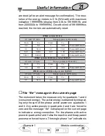
The “Err” message

21

19

Dimensions, panel cut-out

27

23

It may be useful to know that the menus displayed by
the instrument depend on  its configuration; e.g.:  the
instrument will not display the menu relevant to the
digital outputs if the optional module is not mounted.

Summary of Contents for WM22-DIN

Page 1: ...working experience of many decades and a wide spread presence all over the world All this because we want our customers to have the top service and the top products Welcome in the Carlo Gavazzi world...

Page 2: ...tput 1 12 Alarm digital output 13 Digital output 2 14 Analogue output 14 Setting of serial communication port address 15 Digital filter 16 Reset of total meter 16 Reset of partial meter 17 Reset of ma...

Page 3: ...ject Index HOW TO USE THE SYMBOLS We suggest you to keep the original packing in case it is necessary to return the instru ment to our Technical Service Department In order to achieve the best results...

Page 4: ...List and description of the displayed measuring pages W VAr PF Hz W dmd VA dmd Total harmonic distortion ex pressed as for the following voltages V L3 V L1 V L2 These pages are available only if THD i...

Page 5: ...harmonic distortion expressed as for the following currents A L3 A L1 A L2 Total kWh energy meter Total kvarh energy meter Partial kWh energy meter Partial kvarh energy meter To begin with Index 3 4 7...

Page 6: ...ns without neutral V L3 V L2 V L1 Err it s displayed in case of wrong connec tions in one of the 3 phases See Useful in formation on page 21 A L3 A L2 A L1 To begin with 4 7 Programming 8 For version...

Page 7: ...out neutral PF L3 PF L2 PF L1 To begin with Displayed pages 5 4 7 Harmonic distortion 11 If displayed in the measuring mode it means the alarm is ON If the serial port module RS422 485 is present then...

Page 8: ...functions menu Change Password This function allows the operator to choose the desired password value from 0 to 1000 Choose the CnG PASS function by means of the and keys then press to modify PASS en...

Page 9: ...s of the and keys and confirm with CT ratio This function allows the user to se lect the value of the CT ratio Exam ple if the CT primary ammeter transformer has a current of 300A and the secondary ha...

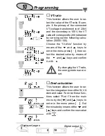
Page 10: ...f the and keys to enter the menu press then se lect the desired value by means of the and keys and confirm it with By changing the VT ratio the energy meters are re set Dmd calculation This function a...

Page 11: ...means of the and keys and confirm with Programming If for example you select the value 15 minutes the instrument calculates the demand value and updates the value every 15 minutes See the diagram bel...

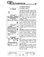
Page 12: ...ns of the and keys and confirm the value with rEA EnE enable the retransmission of the reactive energy by means of pulses confirm it with and then set the number of pulses see table on page 21 by mean...

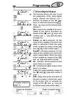
Page 13: ...variable by means of the and keys and confirm with Set oFF off alarm set point it s the value of the variable over which the alarm is deactivated Select the value of the variable by means of the and k...

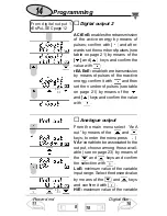
Page 14: ...page 21 by means of the and keys and confirm the value with Programming From digital output 1 rEn PuL SEC page 12 1 2 2 1 1 2 2 1 Power dmd 11 8 18 Digital filter 16 Analogue output From the main men...

Page 15: ...th LoA value of the zero of the output range 0 20mA 0 10V that is generated by the minimum meas ured value LoE Select the desired value by means of the and keys and confirm it with HiA value of the fu...

Page 16: ...er the menu press There are two parameters rnG to set the operating range of the digital filter The value is ex pressed as of the full scale value setthedesiredvalue from0to100 by means of the and key...

Page 17: ...and keys no dmd to avoid the reset or YES dmd to confirm it Then press to carry out the command Reset of partial meters Select rESEt Prt from the main menu by means of the and keys confirm with when t...

Page 18: ...nt the pro gramming by key pad It s possible to prevent access to programming by modifying the dip switch under slot B Set dip switch 1 in position ON to inhibit program ming Set dip switch 1 in posit...

Page 19: ...is AO2920 from 0 to 20mA the instrument must be set as follows VAr variable W system active power LoE minimum electrical scale 0 0 K the K and M multiples are automatically selected by the instrument...

Page 20: ...8V Theparametersofthedigitalfilteraretobeset as follows rnG the variable varies within the average value the ampli tude of which is equal to 1 3 of the variable s rated value calculated as follows 228...

Page 21: ...e A 0 9 0 2 n o i s r e v 2 2 M W o i t a r T V o i t a r T C h W k s e s l u p e g n a R h r a v k m o r F o T m o r F o T 0 1 0 5 1 0 0 1 h r a v k h W k s e s l u P C A V 0 6 6 n o i s r e v y l n...

Page 22: ...ed by the instrument but can be retransmitted by the analogue or RS422 485 output and can be controlled by means of the alarm always without sign The L or C type are displayed with the PF phase variab...

Page 23: ...a t l o v m e t s y S F P r o t c a f r e w o p m e t s y S d H t V n o i t r o t s i d c i n o m r a h l a t o t e g a t l o V d H t A n o i t r o t s i d c i n o m r a h l a t o t t n e r r u C Y S...

Page 24: ...t cover of WM22 press contemporane ously the four release levers at the four angles of the instru ment as shown above Module 2 Slot B Module 1 Slot A Auxiliary power supply Measuring inputs Neutral in...

Page 25: ...p o 0 0 9 2 O A e t o m e r r o m r a l a e s l u p t u p t u o e u g o l a n a 1 2 9 2 O A 0 2 9 2 O A t u p t u o l a i r e s 0 5 9 2 R A 5 8 4 2 2 4 S R OPEN COLLECTOR OUTPUT AO 2900 ANALOGUE OUTPU...

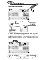
Page 26: ...the modules use a screwdriver Insert the screw driver in the slot on the side of the removable modules as indicated in the figure above Use the screwdriver as a lever to take out the module For the se...

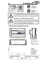
Page 27: ...ccess to programming DENIED Available Modules 25 33 5A Electrical Connections 31 Installation 24 To configure the instrument correctly it is impor tant to verify that dip switch 1 is in position OFF W...

Page 28: ...2 485 Serial port connections 0 20mA output 0 10V output 2 wire connections The grounds of the outputs are separate so that it s possible to carry out two different connections for the same module The...

Page 29: ...tion with neutral 3 wire system Unbalanced load Auxiliary power supply LOAD LOAD Installation 24 5A Electrical connections 33 Dimensions panel cut out 27 33 The termination of the serial output is car...

Page 30: ...g 3 direct connection with without neutral 3 wire system Unbalanced load Note the neutral in the self supplied version must always be con nected to the instrument Installation Available modules 25 33...

Page 31: ...g 6 3 phase CT connection without neutral Unbalanced load Auxiliary power supply LOAD In the DUAL PHASE SYSTEMS both the voltage inputs and the current inputs of phase 1 and 2 must be connected and th...

Page 32: ...al 3 wire system Unbalanced load Auxiliary power supply Fig 9 CT and VT connection with neutral 3 wire systems Unbalanced load LOAD Auxiliary power supply Installation Panel cut out 27 24 Technical fe...

Page 33: ...functions 38 Fig 10 CT and VT connection without neutral 3 wire system Unbalanced load Fig 11 CT and VT connection without neutral 3 wire system Unbalanced load 5 A Version Electrical Diagrams Auxili...

Page 34: ...C 5 C R H 90 1 RDG 1dgt PF 1 0 1Ib to Imax in the range Un Energies 25 C 5 C R H 90 Class 1 according to EN61036 class 2 according to EN61268 Measuring inputs Ib 5A Imax 10A 0 1Ib 500mA start up curre...

Page 35: ...Min 0 Measurements Current voltage power energy power factor frequency harmonic distortion see display specifications TRMS measurement of distorted wave forms Coupling direct Crest factor Ib 5A 3 15A...

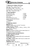
Page 36: ...r current up to the 7th harmonic voltage up to the 7th harmonic Harmonic distortion THD VL1 THD VL2 THD VL3 THD AL1 THD AL2 THD AL3 Display THD System the harmonic distortion can be measured both on 3...

Page 37: ...c and dynamic variables Connections 2 or 4 wires max distance 1200m termina tion directly on the instrument Addresses 255 key pad selectable Protocol MODBUS JBUS Data bidirectional dynamic reading onl...

Page 38: ...ber of outputs 1 Alarm type maximum or minimum phase asymmetry phase loss Set point can be modified from 0 to 100 of the electrical scale Hysteresis can be modified from 0 to 100 of the electrical sca...

Page 39: ...t fundamental variables V A W and derived variables Display up to 4 variables page System variables Page 1 W var PF cos Page 2 W med VA med Hz Single phase variables Page 3 THD V Page 4 THD A System v...

Page 40: ...he limits of CISPR 14 and CISPR 22 pulse volt age 1 2 50 s 8kV EN61000 4 5 Standards safety IEC664 1 energy metrology measurement EN61036 EN61268 pulse output DIN43864 Approvals CE Connections 5 10 A...

Reviews: