

•
Initially set the potentiometers as follows:
DEADBAND………………. Mid-range
IR COMP……… Full counter clockwise
FWD MAX………………… Mid-range
REV MAX……………….… Mid-range
FWD C.L….…………… Full clockwise
REV C.L……………….. Full clockwise
FWD ACCEL……………… Mid-range
REV ACCEL………………. Mid-range
FWD DECEL……………… Mid-range
REV DECEL………………. Mid-range
STEP 2:
With no load on the motor or machine, apply line voltage and close the ENABLE contact to start the
control. Apply maximum forward (positive) reference input. Measure the motor speed or armature
voltage and adjust the FWD MAX pot for base speed or rated armature voltage.
STEP 3:
Repeat the Step 2 procedure for the reverse direction by applying maximum reverse (negative) reference
and adjusting the REV MAX pot.
STEP 4:
(Armature feedback only – Omit this step if tachometer feedback is used.)
•
Adjust the speed (either direction) to mid-range or if known the speed at which the motor will be
run most often. Closely note the motor or line speed. Apply rated or normal load to the motor.
The speed will usually drop a small percentage. Increase the IR COMP pot rotation clockwise until
the loaded speed matches the unloaded speed. Recheck the unloaded speed level and repeat this
step until there is no difference from no load to full load.
•
NOTE:
The IR COMP signal may affect the maximum speed settings. After setting the IR COMP,
recheck each direction’s MAX level and readjust if necessary.
STEP 5:
(Tachometer feedback only – Omit this step if armature feedback is used.)
•
With the control in Armature feedback, run the motor forward (positive reference) and measure
the tachometer voltage at TB1 – 10 & 11. Verify that terminal 10 is positive with respect to
terminal 11 and reverse the leads to correct if necessary.
•
Remove power from the control and switch from the ARM to TACH position.
•
NOTE:
The maximum speed settings may change slightly because of variations in the tachometer
voltage. Recheck and readjust the MAX pots if necessary.
STEP 6:
•
The C.L. (CURRENT LIMIT) pots are normally adjusted to full clockwise to allow 190% of the
amperage level selected by jumper J1 on the Control Board. The RCP200 Series controls can safely
handle this current level on an intermittent basis, i.e. during rapid accelerations and decelerations
or upon application of a cyclic or stepped load. If desired, the maximum current levels can be
limited to a lower level by rotating the C.L. pots counter clockwise.
•
NOTE:
Precise setting of the Current Limit setpoints requires the insertion of a D.C. ammeter in
series with the motor armature.
Carotron RCP200 Series Page 11
Summary of Contents for RCP200 Series
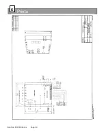
Page 14: ...Prints 6 Carotron RCP200 Series Page 14 ...
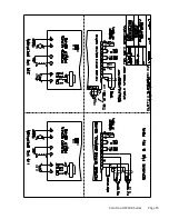
Page 15: ...Carotron RCP200 Series Page 15 ...
Page 18: ...Carotron RCP200 Series Page 18 ...
Page 19: ...Carotron RCP200 Series Page 19 ...
Page 21: ...Carotron RCP200 Series Page 21 ...
Page 22: ...Carotron RCP200 Series Page 22 ...
Page 23: ...Carotron RCP200 Series Page 23 ...
Page 24: ...Carotron RCP200 Series Page 24 ...


