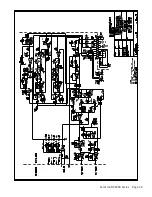
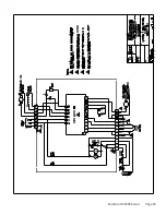
Carotron RCP200 Series Page 17
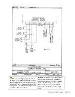
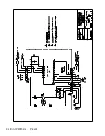
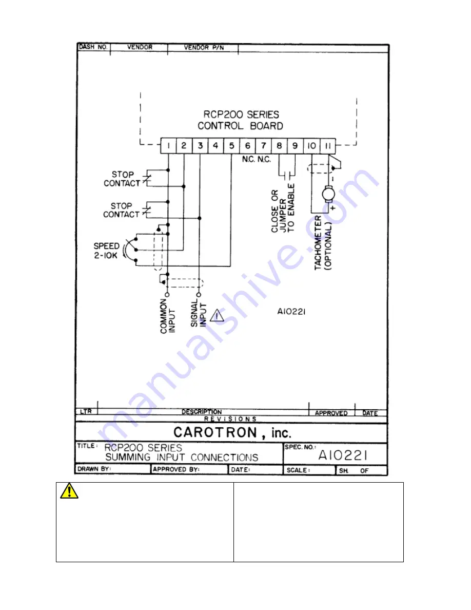
The Summing Input Signal should not
exceed ±10 VDC. Signal connected to TB1-2.
Both Input signals are referenced to Circuit
Common at TB1-1. Like Polarity Signals will
add together and unlike Polarity Signals will
subtract or offset each other.
Example:
+5 VDC at TB1-2 and +5 VDC at
TB1-3 would cause approximately the
same output as +10 VDC at either single
input. +10 VDC at TB1-2 and -5 VDC at
TB1-3 would cause approximately the
same output as +5 VDC at either single
input.
Summary of Contents for RCP200 Series
Page 14: ...Prints 6 Carotron RCP200 Series Page 14 ...
Page 15: ...Carotron RCP200 Series Page 15 ...
Page 18: ...Carotron RCP200 Series Page 18 ...
Page 19: ...Carotron RCP200 Series Page 19 ...
Page 21: ...Carotron RCP200 Series Page 21 ...
Page 22: ...Carotron RCP200 Series Page 22 ...
Page 23: ...Carotron RCP200 Series Page 23 ...
Page 24: ...Carotron RCP200 Series Page 24 ...


