background image


Carotron RCP200 Series        Page 24 

Summary of Contents for RCP200 Series

Page 1: ...Instruction Manual Model RCP202 000 Model RCP205 000 Model RCP202 BC1 Model RCP202 BC2 Model RCP205 BC2 RCP200 Series Motor Controls ...

Page 2: ... we ve developed since 1984 when we pulled together people experienced in product design manufacturing quality control and customer service to provide quality motor control products to the industrial market Today through our innovative design and quality workmanship we are proud that we have become one of the industry s most trusted names in industrial control products We hope that your new RCP200...

Page 3: ... Programming Jumpers Control Board 9 4 3 Potentiometers 9 4 4 Adjustment Procedure Speed Regulator 10 4 5 Adjustment Procedure Torque Regulator 12 5 Spare Parts List 13 6 Prints 14 6 1 C10216 14 6 2 C10217 15 6 3 C10220 16 6 4 A10221 17 6 5 C10184 18 6 6 C10166 19 6 7 D10182 20 6 8 C10165 21 6 9 C10707 22 6 10 C10375 23 6 11 C10328 24 6 12 C10282 25 3204 Rocky River Road Heath Springs SC 29058 Pho...

Page 4: ...of three methods 1 Coast to stop 2 Controlled deceleration to stop 3 Rapid stop in current limit A hard firing high frequency multipulse gating circuit I C regulated power supplies metal film resistors and cermet potentiometers for stable operation under varying conditions of temperature and line voltage On board A C line fuses Oversized power handling components Line transient suppression by MOV ...

Page 5: ...s or 4 20 seconds Deceleration forward and reverse Independently adjustable over either of two selectable ranges 1 5 seconds or 4 20 seconds Note Although the Accel and Decel pots are independently adjustable both pots for a particular direction will have the same time range as programed by J4 or J5 Deadband Zero to 2 volts of Velocity Loop Integrator output I R Comp Range set by Arm Amps jumper J...

Page 6: ...S 15 AMP TRM 2 230 VAC 15 0 AMPS 20 AMP TRM NOTE Fuses shown are manufactured by Gould Littelfuse type FLM may be used as a substitute Control Model RCP205 HP Input Voltage Input A C Current F L Recommended Fuse 3 230 VAC 22 AMPS 35 AMP SC 5 230 VAC 34 AMPS 40 AMP SC NOTE Fuses shown are manufactured by Bussman Littelfuse type SLC may be substituted 3 2 Connection Information Refer to the RCP200 S...

Page 7: ...is terminal is the common connecting point for all reference input signals and reference wiring shields Any reference input signals can be disabled by connecting them to this point WARNING Shield leads connected to COMMON must be insulated at both ends TB1 2 REF IN A signal applied here will have its rate of change controlled by the ACCEL and DECEL pots A positive signal rate of change is controll...

Page 8: ... function normally Opening this contact while running will shut off the control circuit and cause the motor to coast to stop TB1 10 TACH Operation of the control in tachometer feedback requires connection of a 7 or 50 VDC per thousand RPM tachometer to terminal 10 When motoring in the Forward direction Positive reference voltage the terminal 10 tachometer voltage should be positive NOTE Use jumper...

Page 9: ...he rating of the tachometer used J3 Operating mode J3 selects control operation as a motor Speed Regulator or as a motor Torque Regulator In the TORQ position torque is controlled by regulating armature current For a linear motor torque with respect to the torque reference the voltage feedback signal should be defeated by placing the ARM TACH switch in the TACH position with no tachometer connecte...

Page 10: ...itiated by decreasing the speed reference or by shorting the REF IN terminal TB1 2 to COM TB1 1 IR COMP IR compensation The IR COMP pot provides a signal proportional to armature current to compensate for motor losses as the motor load increases This improves speed regulation in armature feedback Clockwise rotation increases the compensation When tachometer feedback is used and when the control is...

Page 11: ...here is no difference from no load to full load NOTE The IR COMP signal may affect the maximum speed settings After setting the IR COMP recheck each direction s MAX level and readjust if necessary STEP 5 Tachometer feedback only Omit this step if armature feedback is used With the control in Armature feedback run the motor forward positive reference and measure the tachometer voltage at TB1 10 11 ...

Page 12: ...R COMP Full counter clockwise FWD MAX Mid range REV MAX Mid range FWD C L Full clockwise REV C L Full clockwise FWD ACCEL Mid range REV ACCEL Mid range FWD DECEL Mid range REV DECEL Mid range NOTE Motor full rated torque is produced at full rated armature current In the following steps motor torque should be monitored directly by use of a D C ammeter connected in series with the motor armature The...

Page 13: ...full torque without overheating Spare Parts List Part Description D10182 00 RCP202 Power Board Assembly D10182 01 RCP205 Power Board Assembly C10184 00 RCP202 Control Board Assembly C10184 01 RCP205 Control Board Assembly PMD1005 00 25A 600V SCR Module for RCP202 PMD1006 00 40A 1200V SCR Module for RCP205 FUS1001 03 TRM 20 Fuse for RCP202 FUS1002 01 SC 40 Fuse for RCP205 5 Carotron RCP200 Series P...

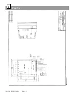
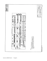
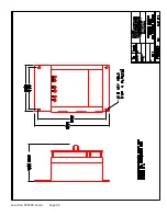
Page 14: ...Prints 6 Carotron RCP200 Series Page 14 ...

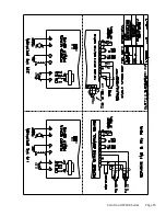
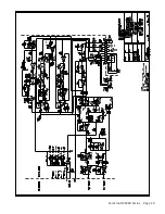
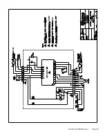
Page 15: ...Carotron RCP200 Series Page 15 ...

Page 16: ...on at TB1 1 Like Polarity Signals will add Together and unlike Polarity Signals will subtract or offset each other Example 5VDC at TB1 2 and 5VDC at TB1 3 would cause approximately the same output as 10VDC at either single input 10VDC at TB1 2 and 5VDC at TB1 3 would cause approximately the same output as 5VDC at either single input Carotron RCP200 Series Page 16 ...

Page 17: ...cuit Common at TB1 1 Like Polarity Signals will add together and unlike Polarity Signals will subtract or offset each other Example 5 VDC at TB1 2 and 5 VDC at TB1 3 would cause approximately the same output as 10 VDC at either single input 10 VDC at TB1 2 and 5 VDC at TB1 3 would cause approximately the same output as 5 VDC at either single input ...

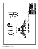
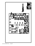
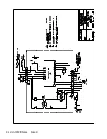
Page 18: ...Carotron RCP200 Series Page 18 ...

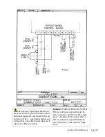
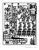
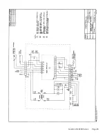
Page 19: ...Carotron RCP200 Series Page 19 ...

Page 20: ...D10182 000 D10182 001 RCP200 SERIES POWER BOARD ISOLATED L1 L2 F1 F2 A1 A2 Carotron RCP200 Series Page 20 ...

Page 21: ...Carotron RCP200 Series Page 21 ...

Page 22: ...Carotron RCP200 Series Page 22 ...

Page 23: ...Carotron RCP200 Series Page 23 ...

Page 24: ...Carotron RCP200 Series Page 24 ...

Page 25: ...Carotron RCP200 Series Page 25 ...

Page 26: ...3204 Rocky River Road Heath Springs SC 29058 Phone 803 286 8614 Fax 803 286 6063 Email saleserv carotron com Web www carotron com MAN1006 00 REV G Issued 10 10 2018 ...

Reviews: