•
Use shielded cable for all speed pot, tachometer, reset and enable wiring. Connect the shield to
circuit common at the control end only. Insulate from ground at both ends. These wires should
be routed away from all A.C. power, armature, field and relay coil wiring.
•
Any relays, contactors, motor starters, solenoids, etc. located in close proximity to or on the same
A.C. line supply as the RCP200 control should have a transient suppression device in parallel with
the coil to minimize interference with the control.
Terminal Connections
•
Power Board Terminals
L1 and L2 (A.C. INPUT):
These terminals are used for the A.C. line input. Either 115 VAC or 230
VAC can be connected to these terminals.
NOTE:
Jumpers J1, J2 and J3 on the Power Board must be placed in the positions corresponding
to the A.C. line voltage used.
F1 and F2 (FIELD):
The motor field leads, F1 and F2, connect to these terminals. No connections
are required when a permanent magnet (P.M.) type motor is used.
A1 and A2 (ARMATURE):
The motor armature leads, A1 and A2, connect to these terminals.
These connections will produce CCW motor rotation as viewed from the commutator end and
with the field connected as shown on the connection diagram. The armature leads should be
reversed if reverse rotation is desired.
NOTE:
When operating in tachometer feedback, the tachometer leads must be reversed when the
armature leads are reversed.
•
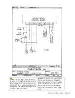
Control Board Terminals (TB1)
TB1 – 1 (COM):
This terminal is the common connecting point for all reference input signals and
reference wiring shields. Any reference input signals can be disabled by connecting them to this
point.
WARNING!
Shield leads connected to COMMON must be insulated at both ends.
TB1 – 2 (REF IN):
A signal applied here will have its rate of change controlled by the ACCEL and
DECEL pots. A positive signal rate of change is controlled by the Forward direction pots and
negative signals are controlled by the Reverse direction pots.
± 10 VDC is the maximum voltage to be applied to this terminal.
Shorting this terminal to COMMON, TB1-1, will cause the motor to decelerate to stop at
the rate determined by the DECEL pot for the respective direction of rotation.
These input signals are internally reset to zero instantly upon closure of a reference reset
contact at TB1-6 & 7.
TB1 – 3 (SUMMING IN):
This terminal connects directly to the Velocity Loop input. Input signals
should not exceed ± 10 VDC and should be disabled by shorting Terminal 3 to COMMON. These
signals are summed with the Terminal 2 reference signals (after their rates have been modified)
and have approximately the same input scaling as the Terminal 2 signals. Like polarity signals at
Terminals 2 & 3 will add together and opposite polarity signals will subtract or offset each other.
NOTE:
The Reference Reset contact will have no affect on signals connected to TB1-3, SUMMING
INPUT.
TB1 – 4 (REV REF):
The negative 10 VDC reference supply here is current limited for protection
during reference shorting operations. Normal load resistance should be 2K ohms or higher.
Carotron RCP200 Series Page 7
Summary of Contents for RCP200 Series
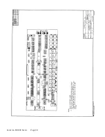
Page 14: ...Prints 6 Carotron RCP200 Series Page 14 ...
Page 15: ...Carotron RCP200 Series Page 15 ...
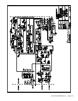
Page 18: ...Carotron RCP200 Series Page 18 ...
Page 19: ...Carotron RCP200 Series Page 19 ...
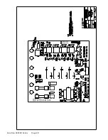
Page 21: ...Carotron RCP200 Series Page 21 ...
Page 22: ...Carotron RCP200 Series Page 22 ...
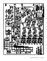
Page 23: ...Carotron RCP200 Series Page 23 ...
Page 24: ...Carotron RCP200 Series Page 24 ...

