Rev. 04/17/03
PARTS BREAKDOWN & OPERATING MANUAL
FEATURES
•
Sturdy Tubular Steel Construction for Strength
•
Multi-Position Locking Mount
•
Adjustable Locking Mechanism Allows 360° Rotation
of Engine
•
T-Shaped Design for Added Stability
•
4 Wheel Design
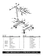
ASSEMBLY INSTRUCTIONS
1.
Bolt front leg (#4) to base connector (#2) using (2)
3/8" x 2-1/2" Hex Bolts (#22), (2) 3/8" washers
(#21), (2) 3/8" lock washers (#20) and (2) 3/8" nuts
(#19). Bolt from outside towards center of
engine stand.
2.
Bolt rear leg (#3) to base connector (#2) using (2)
3/8" x 2-1/2" Hex Bolts (#22),(2) 3/8" washers
(#21), (2) 3/8" lock washers (#20) and (2) 3/8"
nuts (#19).
3.
Insert post (#1) into post tube on base connector
(#2) using a 1/2" x 4" full thread bolt (#25). Screw
into welded nut on post tube, through post (#1)
until tight.
4.
Insert head (#5) into rotator tube on top of post.
Tighten with 1/2" x 1" hex head bolt (#16) screwed
into rotator tube.
5.
Insert handle (#8) through rear of head tube.
6.
Place grips (#9) on both ends of handle.
7.
Attach fingers (#6,7) to head plate using (4) 1/2" x
3" hex head bolts (#23), (4) washers (#24) and (4)
nuts (#18).
INSPECTION
Visual inspection should be made before each use of
the engine stand, checking for damaged, loose or
missing parts. Each stand must be inspected by a
manufacturer’s repair facility immediately, if accidentally
subjected to an abnormal load or shock. Any stand
which appears to be damaged in any way, found to be
badly worn, or operates abnormally
MUST BE
REMOVED FROM SERVICE
until necessary repairs are
made by a manufacturer’s authorized repair facility. It is
recommended that an annual inspection of the stand be
made by a manufacturer’s authorized repair facility and
that any defective parts, decals or warning labels be
replaced with manufacturer’s specified parts.
A list of authorized repair facilities is available from
the manufacturer.
SPECIFICATIONS
Capacity ............................................750 Lbs.
Length ..................................................32-1/2"
Width ....................................................28-/12"
Height ........................................................38"
Shipping Wt...........................................59 lbs.
OPERATING INSTRUCTIONS
Drain oil and coolant and remove flywheel from engine
before mounting. Mount engine as directed in
procedures which follow. Refer to engine service
manuals and technical bulletins when mounting engines.
Lift engine (block) with crane or hoist until even with
head of engine stand. Bolt through adjustable fingers to
back of block at bell housing mounting holes. Fasten
securely to mounting plate. Slowly lower crane or hoist
so that the engine stand supports full weight of engine.
To check engine balance, carefully loosen hex bolt at
back of rotating head, making sure stand is secured
from tipping, and turn handle to rotate engine. If balance
is not satisfactory, rotate engine to its original position
and raise with crane or hoist just enough to take weight
off the stand. Loosen bolts on adjustable fingers and
realign so that weight is evenly distributed. Tighten all
bolts securely and recheck balance. For safe and
secure operation: do not rotate engine more than 90° for
any one location of the positioning handle. In general,
keep the handle within 45° of horizontal. Keep a firm
hold on positioning handle while rotating engine. To
remove an engine from stand, attach a crane or hoist
and raise engine just enough to take engine weight off
stand. Carefully remove bolts attaching fingers to
engine. Be aware that there will be a slight movement of
stand as total engine weight is transferred to crane.
DO NOT CRAWL UNDER ENGINE OR PLACE ANY
PART OF YOUR BODY UNDER ENGINE AT ANY
TIME DURING MOUNTING OF ENGINE, USE OF
STAND, OR REMOVAL OF ENGINE.


