BROADway - Release 4.00
2-7
Installation
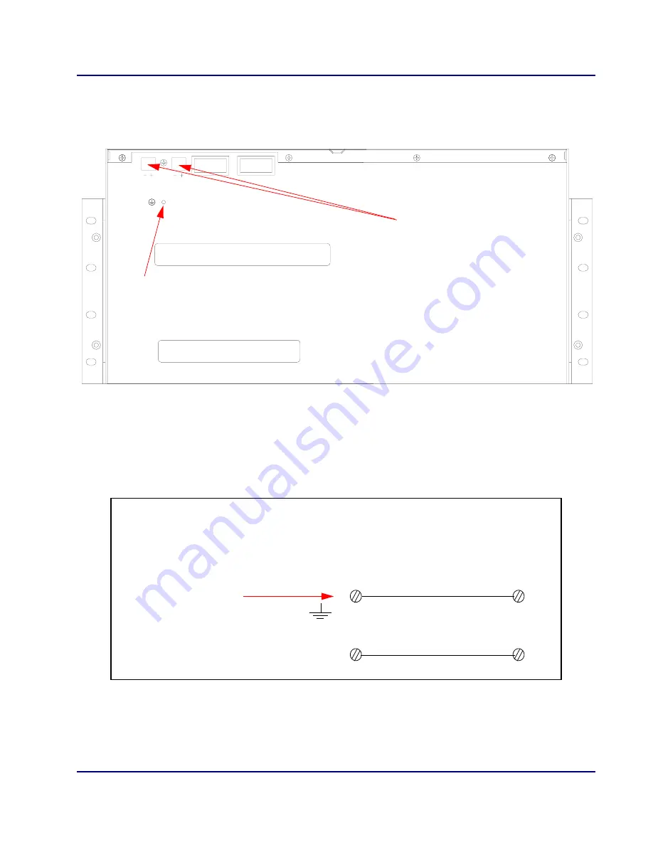
Cabling Power and Ground
3. On the back of the chassis are two separate DC feeds (
FEED A
and
FEED B
).
Remove the green connector from the
FEED A
plug.
4. Attach the appropriate leads to the connector. Your power wires will originate from your DC
power source.
How you attach the leads varies based on whether you are using a -48 V DC ground referenced
power source, or a +24 V DC ground referenced power source.
CONNECTION INFORMATION
FOR +24VDC: 24V to +, RTN to -
FOR -48VDC: RTN to +, -48V to -
+24/-48 VDC, 10 A
THIS UNIT MAY CONTAIN A CLASS 1 LASER PRODUCT WHICH
CONFORMS TO THE APPLICABLE REQUIREMENTS OF 21 CFR
SUBCHAPTER J. REFER TO THE INSTALLATION MANUAL.
FEED A
FEED B
CAUTION: THIS UNIT HAS MORE THAN ONE POWER SUPPLY CONNECTION.
DISCONNECT BOTH POWER SUPPLY CONNECTIONS BEFORE SERVICING TO
AVOID ELECTRIC SHOCK.
OFF
O
POWER A
POWER B
ON
I
OFF
O
ON
I
Connect to Earth ground
Connect to +24VDC or -48VDC power source
BROAD
way Chassis Rear Panel View
BROAD
way
-48 VDC Feed
+
-
RETURN
-48 VDC
Ground at power source
Using a -48 VDC Power Source
Summary of Contents for BROADway System 770-0125-AB
Page 1: ...BROADway INSTALLATION MANUAL Part Number 770 0125 AB Product Release 4 00 March 2004 ...
Page 10: ...x BROADway Release 4 00 Preface Third Party Software Notices ...
Page 14: ...xiv BROADway Release 4 00 Table of Contents ...
Page 15: ...CHAPTER 1 Introduction In This Chapter Overview ...
Page 59: ...BROADway Release 4 00 3 11 Configuration Logging In With the Web Browser Interface GUI ...


