16-8
Axxius 800 - Release 2.2
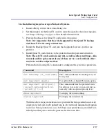
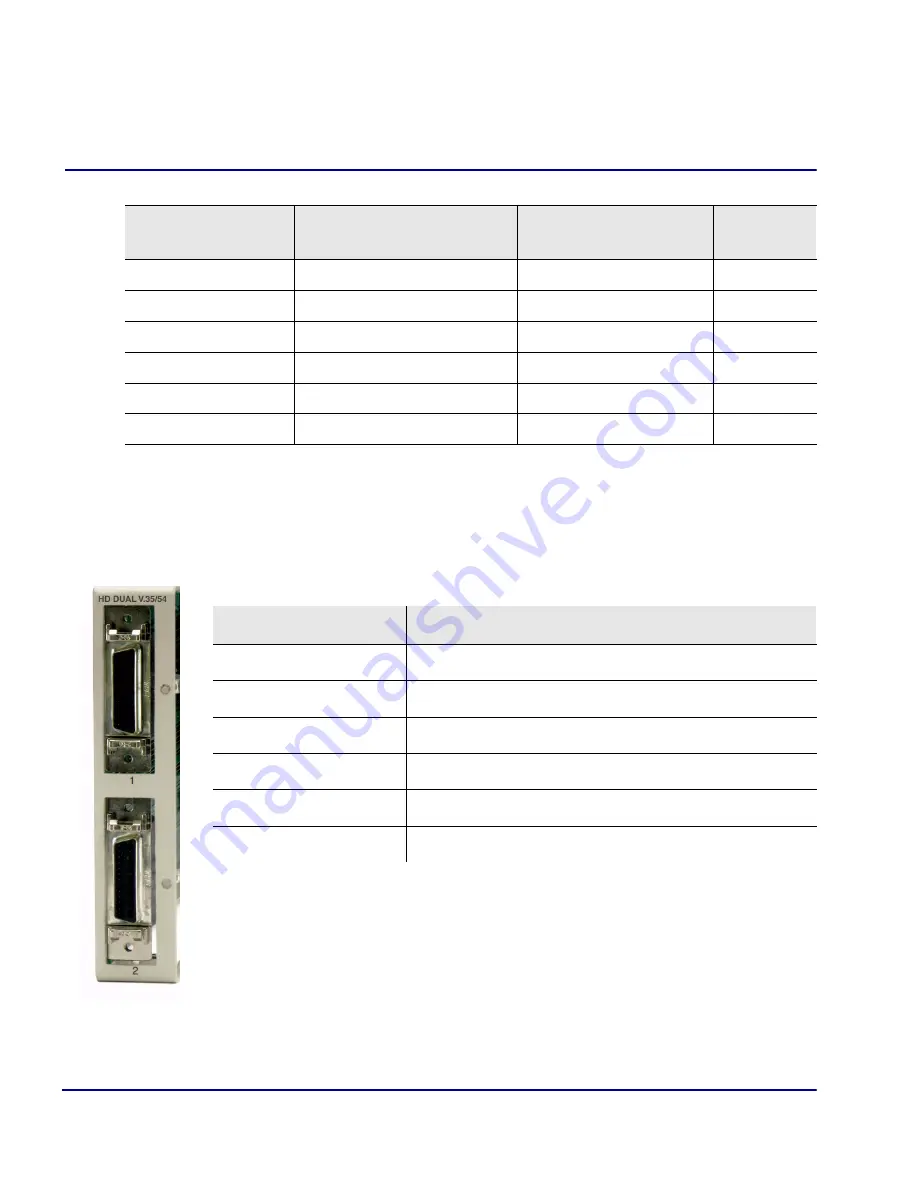
V.35/.54 Card
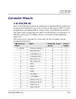
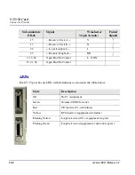
Connector Pinouts
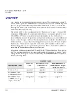
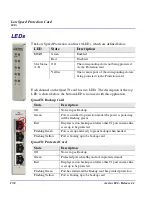
LEDs
Each V.35 port has an LED, with definitions as shown in the table below.
Sub-miniature
DB-26
Signal
Winchester
34-pin (female)
Paired
Signals
15
Receive Clock A
→
V
17
Receive Clock B
→
X
22
←
Local Loopback
J
25
←
Remote Loopback
BB
9, 13, 18
Open Pins/No Contact
L, N, NN
19, 21, 26
Open Pins/No Contact
State
Description
Off
No T1 Assignment
Green
Normal (CD/RTS) Active
Red
CD inactive (T1-side failure)
Yellow
RTS inactive (equipment-side failure)
Flashing Yellow
Loopback toward T1 or equipment loop test
Flashing Green
Loopback toward equipment or network loop test
Summary of Contents for Network Device Axxius 800
Page 1: ...Axxius 800 USER MANUAL Part Number 770 0104 AG Product Release 2 2 May 2004 ...
Page 32: ...xxxii Axxius 800 Release 2 2 Table of Contents ...
Page 50: ...1 18 Axxius 800 Release 2 2 Base Platform ACO ...
Page 101: ...CHAPTER CLI Commands In this Chapter n Command Line Interface Help n CLI Commands ...
Page 392: ...8 8 Axxius 800 Release 2 2 FXO Voice Card Channel Associated Signaling CAS Conversions ...
Page 430: ...12 8 Axxius 800 Release 2 2 Power Supply Installing Replacing a Power Supply ...
Page 472: ...15 20 Axxius 800 Release 2 2 Terminal Server Router Card LEDs ...
Page 500: ...18 12 Axxius 800 Release 2 2 Maintenance Hot Swap Service Card ...
Page 532: ...C 22 Axxius 800 Release 2 2 Loopback Tests V 35 V 54 Loop ...
Page 552: ...Glossary 20 Axxius 800 Release 2 2 Glossary ...

