3-8
Axxius 800 - Release 2.2
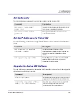
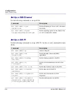
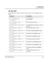
Electrical Installation and Cabling
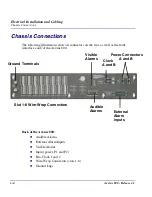
Chassis Connections
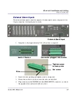
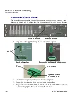
5. Ensure that no bare wire shows after the wires are installed.
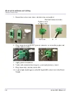
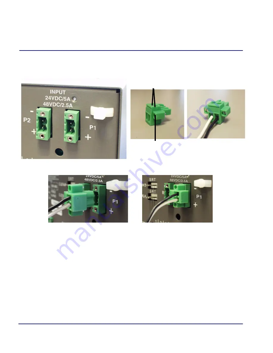
6. Plug connector in the INPUT (power) connector, as seen in the graphic and
secure with set screws.
7. Apply power to connector.
8. Verify with voltmeter that voltage is correct and polarity is correct.
9. Plug connector(s) into the Axxius 800.
10. A green light should appear on the DC Input LED on the front of the Power
Supply.
Provided Connector (male)
+
Set Screw
Tighten screws
to clamp wires
-
Summary of Contents for Network Device Axxius 800
Page 1: ...Axxius 800 USER MANUAL Part Number 770 0104 AG Product Release 2 2 May 2004 ...
Page 32: ...xxxii Axxius 800 Release 2 2 Table of Contents ...
Page 50: ...1 18 Axxius 800 Release 2 2 Base Platform ACO ...
Page 101: ...CHAPTER CLI Commands In this Chapter n Command Line Interface Help n CLI Commands ...
Page 392: ...8 8 Axxius 800 Release 2 2 FXO Voice Card Channel Associated Signaling CAS Conversions ...
Page 430: ...12 8 Axxius 800 Release 2 2 Power Supply Installing Replacing a Power Supply ...
Page 472: ...15 20 Axxius 800 Release 2 2 Terminal Server Router Card LEDs ...
Page 500: ...18 12 Axxius 800 Release 2 2 Maintenance Hot Swap Service Card ...
Page 532: ...C 22 Axxius 800 Release 2 2 Loopback Tests V 35 V 54 Loop ...
Page 552: ...Glossary 20 Axxius 800 Release 2 2 Glossary ...


