(3) Procedure
a) Perform air purging from the Chiller until inside pressure of the Chiller reaches allowable
degree of vacuum, after that, continue air purging for at least one hour.
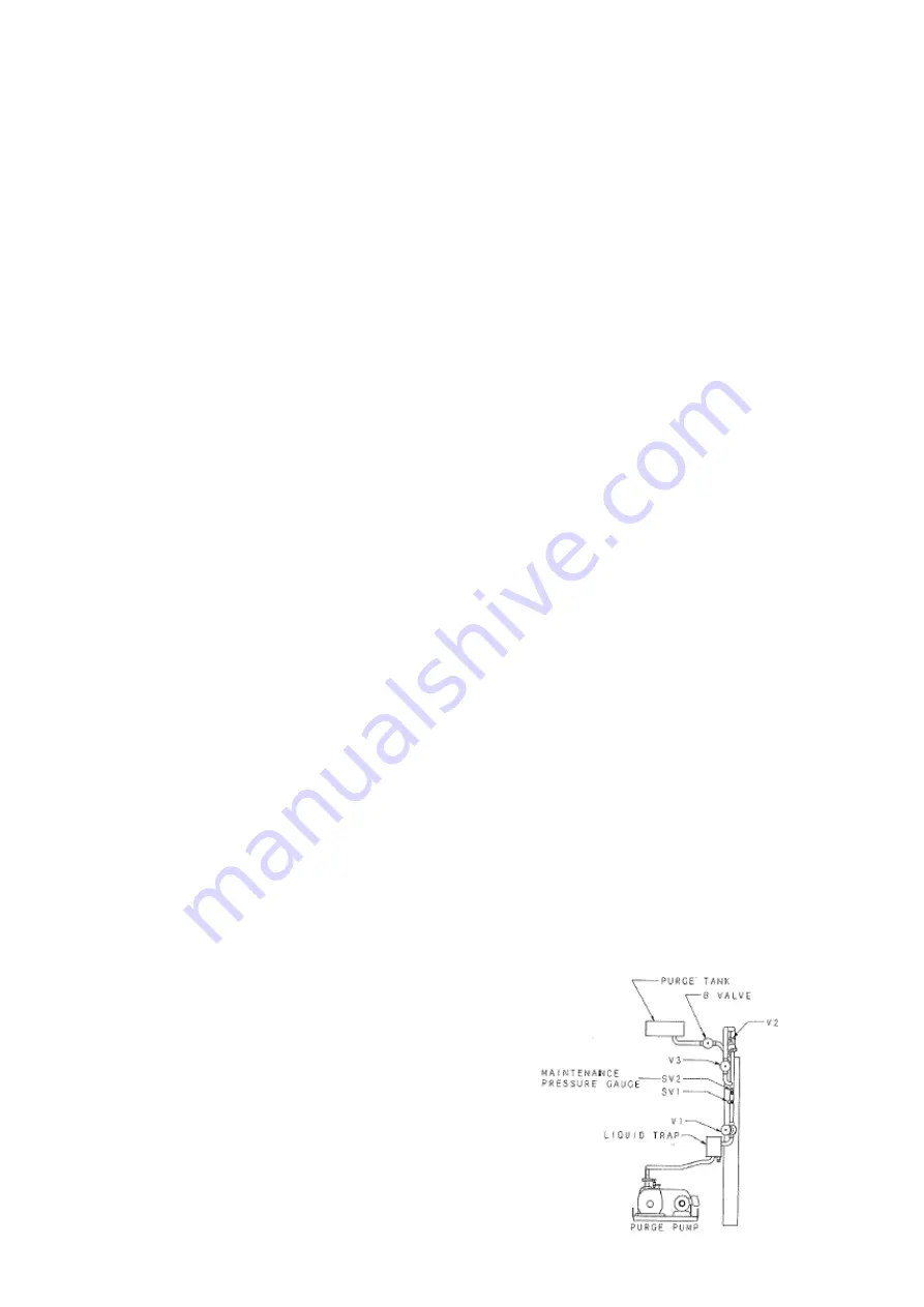
b) Connect vacuum gauge to SV2, and open SV2.
c) Make sure that the attained vacuum of the purge pump is under 5hPa.
d) Remove an exhaust port cap of the purge pump, and install the attachment to the
exhaust port and furnish a vinyl hose to the attachment as shown in Fig. 1-11-7.
e) Open V1, close V2 and V3.
f)
Continue to operate the purge pump for one minute under the condition as mentioned
above. Then measure volume of bubbles. During this measuring, keep the position of
the vinyl hose within 10mm in depth. If bubbles are collected, inspect and tighten the
downstream connections from V2 and V3. If bubbles are still generated in spite of the
tightening, measure its volume collected for 10 minutes.
g) Open V1 and V3, Close V2.
* A gas ballast valve and an oil delivery valve should be closed.
h) Continuing operation of the purge pump under the above condition, measure volume of
bubbles for 10 minutes. The measurement should be repeated at least three times.
During these measurement, attained vacuum of the purge pump shall be kept below
4 mmHg.
i)
The measured volume in item f) is called as " A cc ", and that in item h) is called as
" B cc ".
( B cc - A cc ) is a result of the bubble test.
j)
After bubble test, gas ballast valve should be opened. And oil delivery valve should be
opened to confirm whether any water is contained in the purge pump oil or not. If the
water is observed, drain the water and fill new oil.
22
Summary of Contents for LJ
Page 1: ...Absorption Chiller INSTALLATION MANUAL LJ Model ...
Page 26: ...Fig 1 11 7 23 ...
Page 30: ... marks are the positions measured by the megger 27 ...
Page 36: ...33 ...
Page 37: ...34 ...
Page 46: ...13 Sampling of absorbent Sampling of absorbent Finished Unfinished 43 ...


