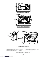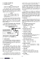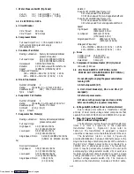
1-11
l. Water Pressure Switch (Optional)
Cut-In:
0.5
¦
0.2 kg/cm
@
(7
¦
3 psig)
Cutout:
1.6
¦
0.4 kg/cm
@
(22
¦
5 psig)
1.4 ELECTRICAL DATA
a. Circuit Breaker
CB-1 Trips at:
29 Amps
CB-2 Trips at:
62.5 Amps
b. Compressor Motor
Full Load Amps (FLA):
17.6 Amps @ 460 VAC
(with current limiting set at 21 amps)
(Model 69NT40)
c. Condenser Fan Motor
Bearing Lubrication:
Factory lubricated, additional
grease not required.
Full Load Amps:
2.6/1.3 @ 190/380 VAC/50 hz
3,2/1.6 @ 230/460 VAC/60 hz
Horsepower:
0.43/50 hz (0.75/60 hz)
Rotation:
CCW when viewed from shaft end.
Speed:
1425/50 hz (1725/60 hz) RPM
Voltage and Frequency:
180 --- 230/360 --- 460 VAC @ 50 hz
¦
1.25 hz
200 --- 250/400 --- 500 VAC @ 60 hz
¦
1.5 hz
d. Drain Pan Heaters
Number of Heaters:
1
Rating:
750 watts +5 /---10 % @ 460 VAC
Resistance (cold):
285
¦
7.5% ohms nominal
Type:
Sheath
e. Evaporator Coil Heaters
Number of Heaters:
4
Rating:
750 watts +5/---10% each @ 230 VAC
Resistance (cold):
66.8 to 77.2 ohms
Ambient:
@ 20
_
C (68
_
F)
Type:
Sheath
f. Evaporator Fan Motor(s)
Bearing Lubrication:
Factory lubricated, additional
grease not required
Full Load Amps
:
High Speed:
1.6 @ 380 VAC/50 hz
(2.1 @ 460 VAC/60 hz)
Low Speed:
0.6 @ 380 VAC/50 hz
(0.6 @ 460 VAC/60 hz)
Single Speed Motor:
3.2/1.6 @ 190/380 VAC/50 hz
(0.58/1.0 @ 230/460 VAC/60
hz)
Nominal Horsepower:
High Speed:
0.58 @ 380 VAC/50 hz
(1.0 @ 460 VAC/60 hz)
Low Speed:
0.07 @ 380 VAC/50 hz
(0.12 @ 460 VAC/60 hz)
Single Speed Motor:
0.58 @ 50 hz
(1.0 @ 60 hz)
Rotation
:
Evap. Fan Motor
#1
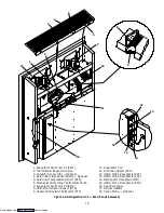
(See Figure 1-2):
CW when viewed from shaft end
CCW when viewed from end opposite shaft end
Evap. Fan Motor
#2
(See Figure 1-2):
CCW when viewed from shaft end
CW when viewed from end opposite shaft end
Speed
:
High Speed:
2850 rpm @50 hz
(3450 rpm @ 60 hz)
Low Speed:
1425 rpm @ 50 hz
(1750 rpm @ 60 hz)
Single Speed Motor:
2850 rpm @ 50 hz
(3450 rpm @ 60 hz)
Voltage and Frequency:
180 --- 230/360 --- 460 VAC @ 50 hz
¦
1.25 hz
200 --- 250/400 --- 500 VAC @ 60 hz
¦
1.5 hz
g. Fuses
Control Circuit:
15 Amps (F3)
Controller:
5 Amps (F1 & F2)
DataCorder:
3 Amps (F)
h. Compressor Crankcase Heater (CCH) Optional
180 watts @ 460 vac
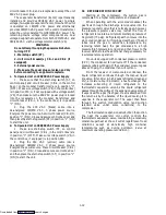
1.5 VOLTAGE SWITCH (OPTIONAL) AND
POWER AUTOTRANSFORMER (OPTIONAL)
WARNING
Do not attempt to unplug the power cable before
turning OFF:
1. Start-stop switch (ST).
2. Unit circuit breaker(s), CB-1 and CB-2 (if
equipped).
3. External power source.
4. Make sure the power plugs are clean and dry
before connecting to any power receptacle.
a. Voltage Switch (without Power Autotransformer)
Dual voltage units without a transformer consist
entirely of dual mains voltage rated components that
operate from both 190/230 VAC and 380/460 VAC power.
b. Step-Up Power Autotransformer
(with or without voltage switch)
The transformer is either the whole-unit transformer
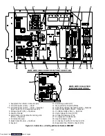
(item 1 or item 3, Figure 1-6) or the evaporator
transformer (item 2, Figure 1-6). (Also refer to
Table 1-1) The transformer (if equipped) is located
under the condenser coil on the left-hand side of the unit.
The transformer (item 1 or item 3, Figure 1-6)
provides 380/460 VAC, 3 phase, 50/60 hertz power to the
single mains voltage rated components of the unit when
the 230 VAC (black) power cable is connected to a
190/230 VAC, 3 phase power source. The transformer
(item 1) may be permanently installed in the unit (with
accompanying voltage selector switch VS) or exist as a
modular transformer (item 3) added to convert a single
voltage (380/460 VAC) unit to dual voltage capability
(without voltage selector switch VS). The module in
addition to the transformer, includes a 230 VAC cable,
Downloaded from


