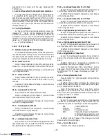
1-16
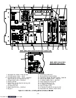
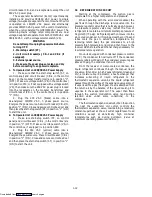
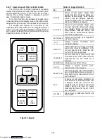
1.12 MICRO-LINK 2 CONTROLLER MODULE
1. Micro-Link 2 Controller Module
2. Battery Pack (Optional)
3. Software Port
4. Connectors
5. Fusess
6. Test Points
7. Control Circuit Power
Connection
8. Status LED
1
2
3
4
5
6
7
4
8
Figure 1-8. Micro-Link 2 Controller Module
1.12.1 Brief Description
WARNING
Do not attempt to service the controller module,
breaking the warranty seal will void the
warranty.
CAUTION
Remove the controller module and unplug all
wire harness connectors before performing any
arc welding on any part of the container.
Do not remove wire harnesses from modules
unless you are grounded to the unit frame with a
static safe wrist strap.
The Carrier Transicold Micro-Link 2 controller is a
custom-designed microprocessor based module which
incorporates electronic logic to:
a. Control supply or return air temperature to extreme-
ly tight limits by providing modulated refrigeration con-
trol, electric heat control and defrost to ensure continu-
ous conditioned air delivery to the load.
b. Provide dual independent readouts of set point and
supply or return air temperatures.
c. Provide digital readout and ability to select data. Re-
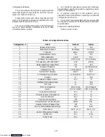
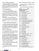
fer to Table 1-6 for Controller Function Codes.
d. For controller alarm digital display identification
refer to Table 1-7.
e. Provide a pre-trip step-by-step checkout of refrigera-
tion unit performance, proper component operation,
proper electronic and refrigeration control operation,
proper heater operation, probe calibration and current
limiting. Refer to section 1.13.
f. Provide the ability to select or change Codes 27 to 37
and set point without AC power being hooked up. Refer
to section 1.12.5.
g. The unit provides memory reprogramability and
configuration through a memory card. The memory card
automatically downloads new software to the controller
when inserted, and controls output to the display of status
information.
h. The Status/Power/Executing code LED indicates if
the Controller is powered up and executing code. The
LEDwill be off when power is off. The LED will pulse at a
one second rate if code is being executed.
1.12.2 Controller Programming (Memory) Cards
The programming cards are used for loading soft-
ware into the Controller. This is the same concept as
using a floppy diskette to load software into a personal
computer.
The software that can be loaded into the Controller
module, comes in one of two forms. Either “Operational
Software” or “Configuration Software.”
Operational Software:
This is the software that makes the Controller mod-
ule do what it does. Turn fans on and off, turn compres-
sors on and off, etc.
Downloaded from

