1-19
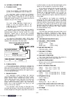
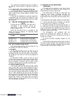
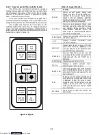
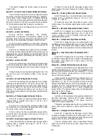
The display module (see Figure 1-10) is mounted at a
20 degree downward tilt to aid in visibility when stacked
in close quarters. The display module consists of:
a. Two --- 25mm (1 inch) high, five digit LCD displays
which are easily viewed in direct sunlight and back-
lighted for superior low-light visibility.
b. Seven (7) Indicators:
D
Cool --- White Lamp:
Lamp energized when the refrigerant
compressor is energized.
D
Heat --- Orange LED:
LED energized when the heaters are on, and the
unit is in the heat or defrost (de-ice) mode.
D
Defrost --- Orange LED:
LED energized when the heaters are on, and the
unit is in the defrost mode.
D
In-Range --- Green LED:
LED energized when the controlling temperature
probe is in range. (Supply air probe will be used
for control in the perishable ranges and the return
air probe is used for control in the frozen ranges.)
D
Alarm --- Red LED:
LED energized when there is an active or an
inactive shutdown alarm (AL20 to AL27) in
the alarm queue.
D
Supply --- Yellow LED:
LED energized when supply temperature and
set point are displayed.
Flashes if dehumidification is enabled on units
so equipped.
D
Return --- Yellow LED:
LED energized when return temperature and
set point are displayed.
Flashes if dehumidification is enabled on units
so equipped.
COOL
HEAT
DEFROST IN RANGE ALARM
SUPPLY
RETURN
SETPOINT/Code
AIR TEMPERATURE/Data
Figure 1-10. Display Module
NOTE
The default display mode will show the set point
temperature on the left display and controlling
probe temperature on the right display. The
controlling probe in the perishable range will be
the SUPPLY air probe and the controlling probe
in the frozen range will be the RETURN air
probe.
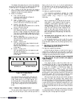
1.12.4 Controller Temperature Control
There are two control ranges, Frozen and Perishable
(chill). The Frozen range is active with set points at or
below ---10
_
C (+14
_
F) or ---5
_
C (+23
_
F) optionally and
the Perishable range is active at set points
above ---10
_
C
(+14
_
F) or ---5
_
C (+23
_
F) optionally. See Figure 1-13
and Figure 1-14.
For Revision Level 1014 and above:
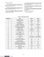
The Controller configuration variable for “Heat
Lockout” (refer to Table 1-4) can be changed for set
points of either ---10
_
C (+14
_
F) or ---5
_
C (+23
_
F)
optionally.
NOTE
When upward set point changes are made the
compressor is immediately cycled through a
reliability enhancement algorithm (SMV is
cycled between 70% to 0%) to remove any
refrigerant trapped in the oil. This also happens
when Current Limiting is first initiated at the
start of P6-0 and P6-4, during Pre-Trip. For
upward set point changes, current limiting and
P6-0, the algorithm is 10 cycles long. For P6-4 it is
5 cycles long.
a. Perishable (chill) range above ---10
_
C (+14
_
F) or
---5
_
C (+23
_
F) optionally.
For set points ABOVE ---10
_
C (+14
_
F) or ---5
_
C
(+23
_
F) optionally, the controller maintains SUPPLY
air at the set temperature by the following modes of op-
eration:
1. Operation in the Conventional Mode without
Dehumidification (Code 33 OFF)
For Revision Level 1014 and above:
If the Condenser Pressure Control (CPC) logic is
enabled, the condenser fan will cycle ON if condenser
pressure is at or above 200 psig and will cycle OFF when
condenser pressure drops below 130 psig.
If the unit starts and condenser pressure is below 200
psig, the condenser fan will not start until pressure
reaches 200 psig.
For All Revision Levels:
The supply probe is used for control and is so
indicated by the “SUPPLY” LED on the display module.
The Perishable temperature range demands high accura-
cy. The unit is capable of maintaining supply air
temperature to within
¦
0.25
_
C (
¦
0.5
_
F) of the set
point temperature setting. In Perishable range
above
---10
_
C (+14
_
F)
or ---5
_
C (+23
_
F) optionally, control is
maintained by controlling the positions of the solenoid
modulation valve (SMV) and suction solenoid valve
(SSV, on 69NT40 only) with compressor energized.
When pulling down to the set point, both valves will
be open to reduce the pulldown time unless suction
solenoid override or current limiting is active. See section
1.10 for explanation of suction solenoid override. The
current limit function will restrict the valves if the current
is above the selected value. When the controlling probe
temperature reaches set point, the suction solenoid valve
will close.
When the controlling probe temperature enters the
in-range temperature tolerance as selected at function
code Cd30, the in-range light will energize.
Downloaded from

