1-23
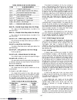
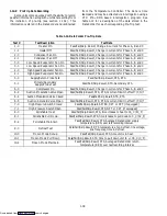
Code 11 --- Compressor Discharge Temperature ---
Optional
The compressor discharge temperature is measured
near the compressor discharge valve.
Code 12 --- Compressor Suction Pressure --- Optional
Compressor Suction Pressure is displayed by using a
pressure transducer.
Code 13 --- Compressor Discharge Pressure or
Condenser Pressure (CPC) --- Optional
Compressor discharge or condenser pressure is
displayed by using a pressure transducer.
Pressure is displayed in units of psig when code 28 is
set to
_
F and units of bars when code 28 is set to
_
C. “P”
appears after the value to indicate psig and “b” appears
after the value to indicate bars.
Code 14 & 15 --- Future Expansion
These codes are for future expansion.
Code 16 --- Compressor Motor Hour Meter
Records total hours of compressor run time. Records
total hours in increments of (10) ten hours (ie. 3000 hours
displayed as 300).
Code 17 --- Relative Humidity (%) --- Optional
This code is only applicable to units with a humidity
sensor (HS). This code displays in percent the relative
humidity at that time.
Code 18 --- Software Revision Number
The software revision number is displayed.
Code 19 --- Battery Check
This code checks the optional battery pack, while the
test is running “btest” will flash on the right display,
followed by the result. “PASS” will be displayed for
battery voltages greater than 7.0 volts, “FAIL” will be
displayed for battery voltages between 4.5 and 7.0 volts,
and “--- --- ---” will be displayed for battery voltages less
than 4.5 volts. After the result is displayed for four
seconds, “btest” will again be displayed, and the user may
continue to scroll through the various codes.
Code 20 --- Configuration ID
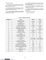
This code indicates the dash number of the model for
which the Controller is configured (i.e., if the unit is a
69NT40-489-62, the display will show 0062).
Code 21, 22, & 23 --- Future Expansion
These codes are for future expansion.
Code 24 --- Secondary Supply Air Temperature ---
Optional
The secondary supply air temperature (for 3 probe
units) is measured at the same place as the primary supply
air temperature.
Code 25 --- Time Remaining Until Defrost
This code displays the time remaining until the unit
goes into defrost (in tenths of an hour).
Code 26 --- Defrost Termination Sensor
The defrost termination sensor is located immedi-
ately above the evaporator coil. It is used by the controller
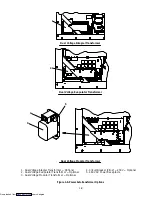
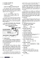
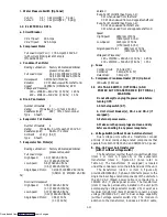
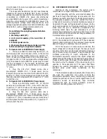
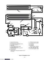
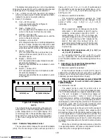
for defrost initiation and termination. (See Figure 1-2)
NOTE
The following are user-selectable functions. The
operator can change the value of these functions
to meet the operational needs of the container.
Code 27 --- Defrost Interval (Hours)
The defrost interval is the time interval between
defrost cycles of which there are 5 possible selectable
values: 3, 6, 9, 12 or 24 hours. The factory default value is
3 hours.
The time interval of the first defrost will not begin
counting down until DTS is below 10
_
C (50
_
F). The time
interval to the next defrost cycle is entered into the
controller at the time DTS is below 10
_
C (50
_
F) or at
power-up. (See code Cd37 for deviations.)
NOTE
The defrost interval timer counts only during
compressor run time.
For Revision Level 1013 and below:
When the interval timer has counted down 2.5 hours,
the relationship between the control temperature and
the set point is checked. If the control temperature is 5
_
C
(41
_
F) above the set point, the unit immediately goes
into the defrost mode. Upon termination of defrost, the
user selected interval (ie., 3, 6, 9, 12 & 24 hr) is reset.
During pulldown from high ambient, this cycle will repeat
until the control temperature is less than 5
_
C (41
_
F)
above the set point. At such time, the selected defrost
interval time will be used.
If the control temperature drifts 5
_
C (41
_
F) above
the set point after the 2.5 hours of countdown but prior to
completion of the selected interval, the unit will immedi-
ately go into defrost. Upon termination of defrost, the
defrost interval timer will be reset.
For All Revision Levels:
If DTS reaches 25.6
_
C (78
_
F) at any time during the
timer count down, the interval is reset and the countdown
begins over.
If DTS has failed (ie., AL60 is active) and the
primary return sensor temperature is less than 10
_
C
(50
_
F), the interval timer countdown begins. The inter-
val timer is reset if the return sensor temperature rises
above 25.6
_
C (78
_
F). (See section 2.4.4.)
Defrost Interval Timer Value Option:
If the software is configured to “ON” for this option,
then the value of the defrost interval timer will be saved at
power down and restored at power up. This option
prevents short power interruptions from resetting an
almost expired defrost interval, and possibly delaying a
needed defrost cycle.
Code 28 --- Temperature Units (
_
C or
_
F)
This code determines the temperature unit’s
_
C or
_
F which will be used for all temperature displays. The
user selects
_
C or
_
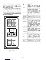
F by selecting code 28 and pushing the
ENTER key. The factory default value is C.
Downloaded from

