1-25
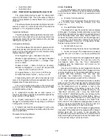
up to 16 alarms in the sequence in which they occurred.
When accessing the alarm list, an “IA” or an “AA” will
appear to the left of the alarm code number. The “IA”
indicates an Inactive Alarm; one that has occurred, but
no longer exists. The “AA” indicates an Active Alarm; one
that is still indicating an improper condition.
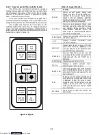
The Alarm List Display Mode is entered by pressing
the ALARM LIST key while in Set Point Selection or
Default Display mode. The user will be able to display
any alarms archived in the Alarm Queue. If no alarms,
other than those related to the EEPROM (AL51), are
active, the Alarm Queue may be cleared.
When the ALARM LIST key is pushed, the left
display will show AL#, where # is the alarm number in
the queue. The right display will shown AAXX, if the
alarm is active, where XX is the alarm number or IAXX,
if the alarm is inactive. The user can look through the
alarm queue by depressing the UP ARROW key. At the
end of the alarm list, if any of the alarm(s) in the list is
active, END is displayed. If all the alarms in the list are
inactive, then at the end of the alarm list, CLEAr is
displayed. (The exception to this rule is the AL51 failure
alarm, this alarm does not have to go inactive in order to
clear the alarm list) At this time if the user pushes the
ENTER key, then the alarm list will clear and display
“--- --- --- ---” on right display. Another alternative for the
user to get to the end of the alarm list is by pushing the
DOWN ARROW key after the ALARM LIST key is
pushed. Thus, the DOWN ARROW key being pushed
will allow the user to go backward in the alarm list. If a
user pushes ALARM LIST key when there are no alarms
in the list, then AL is displayed on left display and
“--- --- --- ---” on the right display. Upon clearing of the
Alarm Queue, the Alarm light will be turned off.
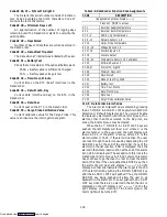
Alarm 20 --- Control Circuit Fuse Open (24 VAC)
Alarm 20 is triggered by fuse (F3) opening and will
cause the software shutdown of all control units. This
alarm will remain active until the 15 amp fuse is replaced.
Alarm 21 --- Micro Circuit Fuse Open (18 VAC)
Alarm 21 is triggered by one of the fuses (F1/F2)
being opened on 18 volts AC power supply to the
controller. SMV will be opened and current limiting is
halted. The compressor will cycle, temperature control
will be obtained by cycling the compressor.
Alarm 22 --- Evaporator Fan Motor Safety
Alarm 22 is triggered by the opening of the evapora-
tor motor internal protector. This alarm will disable all
control units until the motor protector resets. Also, refer
to code Cd29.
Alarm 23 --- Auto Transformer Safety --- Optional
Alarm 23 is triggered by the auto transformer
internal protector opening, and will result in the disabling
of all control units except the evaporator fans. The alarm
will stay active until the transformer protector resets. On
units with dual voltage evaporator transformer (refer to
Table 1-1), Alarm 23 is triggered by the internal protector
opening, and will result in the disabling of all control
units. The alarm will stay active until the transformer
protector resets.
Alarm 24 --- Compressor Motor Safety
Alarm 24 is triggered by the opening of the compres-
sor motor internal protector. This alarm will disable all
control units except for the evaporator fans and will
remain active until the motor protector resets.
Alarm 25 --- Condenser Fan Motor Safety
Alarm 25 is triggered by the opening of the condens-
er motor internal protector and will disable all control
units except for the evaporator fans. This alarm will
remain active until the motor protector resets. This alarm
is deactivated if the unit is operating on water cooled
condensing.
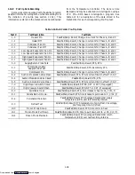
Table 1-7. Controller Alarm Indications
NO.
ALARM DESCRIPTION
AL20
Control Circuit Fuse Open (24 VAC)
AL21
Micro Circuit Fuse Open (18 VAC)
AL22
Evaporator Fan Motor Safety
AL23
Auto Transformer Safety
AL24
Compressor Motor Safety
AL25
Condenser Fan Motor Safety
AL26
All Supply and Return Air Sensor Failure
AL27
Probe Circuit Calibration Failure
AL51
Alarm List Failure
AL52
Alarm List Full
AL53
Mains Voltage Sensor Failure
AL54
Primary Supply Air Sensor Failure
AL55
Secondary Supply Air Sensor Failure
AL56
Primary Return Air Sensor Failure
AL57
Ambient Temperature Sensor Failure
AL58
Compressor High Pressure Safety
AL59
Heat Termination Thermostat (HTT) Safety
AL60
Defrost Termination Sensor Failure
AL61
Heaters Failure
AL62
Compressor Circuit Failure
AL63
Current Over Limit
AL64
Discharge Temperature Over Limit
AL65
Discharge or Condenser Pressure Sensor Failure
AL66
Suction Pressure Sensor Failure
AL67
Humidity Sensor Failure
ERR #
Internal Microprocessor Failure
Entr stpt Enter Setpoint (Press Arrow & Enter)
LO
Low Mains Voltage
VENT
VENT mode - Controlled Atmosphere (CA) option
P-CA
Pre-Trip mode - Controlled Atmosphere (CA) option
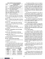
Alarm 26 --- All Supply and Return Air Sensor Failure
Alarm 26 is triggered if the controller determines
that all of the control sensors are out-of-range. This can
occur for box temperatures outside the range of ---50
_
C
to +70
_
C (---58
_
F to +158
_
F).
Downloaded from

