4-14
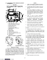
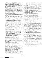
10.79 CM
(4.25 INCHES)
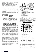
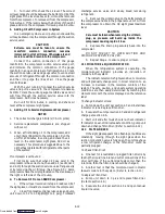
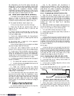
Figure 4-18. Evaporator Fan Locating Dimension
e. Connect wiring per applicable wiring diagram and
install motor and fan assembly in unit. Apply power,
momentarily, to check fan rotation. (Refer to section
1.4.) If fan spins backwards, refer to section 4.25 for
two-speed motors.
Replace access panel, making sure panel does not
leak. Make sure that the T.I.R. locking device is
lockwired.
4.16 EVAPORATOR COIL HEATERS
WARNING
Before servicing unit, make sure the unit circuit
breakers (CB-1 & CB-2) and the start-stop
switch (ST) are in the OFF position. Also
disconnect power plug and cable.
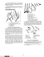
a. Remove the lower access panel (Figure 1-1) by
removing the T.I.R. locking device lockwire and
mounting screws.
b. Determine which heater(s) need replacing by
checking resistance on each heater as shown in section
1.4.e.
c. Remove hold-down clamp securing heaters to coil.
d. Lift the “U” portion of the heater (with opposite end
down and away from coil). Move heater left (or right)
enough to clear the heater end support.
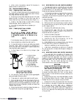
4.17 CONDENSER COIL
The condenser consists of a series of parallel copper
tubes expanded into copper fins. The condenser coil must
be cleaned with fresh water or steam, so the air flow is not
restricted. Fan rotation is counterclockwise when viewed
from shaft end of motor.
WARNING
Do not open the condenser fan grille before
turning power OFF and disconnecting power plug.
To Replace Condenser Coil:
a. Remove the refrigerant charge per section 4.3.
b. Remove the condenser coil guard.
c. Unsolder discharge line and remove the line to the
water-cooled condenser (if so equipped).
d. Remove coil mounting hardware and then remove
the coil.
e. Install replacement coil and solder connections.
f. Leak check the coil per section 4.4. Evacuate the unit
per section 4.5 and then, charge the unit with refrigerant
per section 4.6.1.
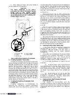
4.18 CONDENSER FAN AND MOTOR ASSEMBLY
WARNING
Do not open condenser fan grille before turning
power OFF and disconnecting power plug.
NOTE
The replacement motor should be degreased
and sprayed with a coat of Tectyl before
installing in unit.
The condenser fan rotates counterclockwise (viewed
from front of unit) and pulls air through the the
condenser coil and discharges horizontally through the
front of the unit.
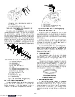
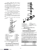
a. Open condenser fan screen guard.
b. Loosen square head set screws (2) on fan. (Thread
sealer has been applied to set screws at installation.)
Then disconnect wiring from motor junction box.
CAUTION
Take necessary steps (place plywood over coil or
use sling on motor) to prevent motor from falling
into condenser coil.
c. Remove motor mounting hardware and replace the
motor. It is recommended that new locknuts be used when
replacing motor. Connect wiring per wiring diagram.
d. Install fan loosely on motor shaft (hub side in). Install
venturi. Apply “Loctite H” to fan set screws. Adjust fan
within venturi so that the outer edge of the fan projects
(7.9 mm = 5/16”) out from edge of venturi. Spin fan by
hand to check clearance.
e. Close and secure condenser fan screen guard.
f. Apply power to unit and check fan rotation. If fan
motor rotates backwards, reverse wires 5 and 8.
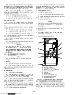
4.19 RECORDING THERMOMETER (PARTLOW)
a. Instruments for Checking Bulb Temperature
The recording thermometer may be equipped with
one or two Simpson accessories (#344 units), each
consisting of a thermistor probe and receptacle
(mounted to instrument case.) Single probe is attached
to the element (bulb) capillary which senses the container
return air temperature. If using two probes, the other
probe is attached to the supply air temperature sensor.
In the event of a failure with the #344 test lead, other
instruments for checking bulb temperatures are:
Simpson Meter, CTC P/N 07-00013 or Robinair Thermistor
Temperature Tester, Model 12860:
A resistance thermometer with RCA lead and a
phono-plug at each end may be used to compare bulb
temperature and stylus indicated temperature on the
chart by inserting one end of the lead into the receptacle
provided on the controller and the other end in the
meter. Always check resistance thermometer before
using. (Refer to para. b.)
Ohmmeter:
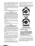
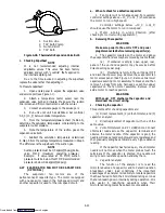
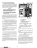
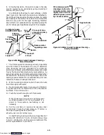
1. Place one probe of ohmmeter in the middle of
the receptacle provided on the chart platen, Figure 4-19,
and ground other probe to unit.
Downloaded from


