4-21
1
2
3
4
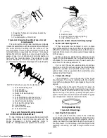
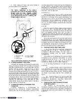
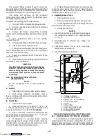
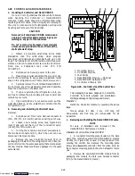
1. Suction Line
2. TXV Bulb Clamp
3. Nut and Bolt
4. TXV Bulb
Figure 4-28. Thermostatic Expansion Valve Bulb
c. Checking Superheat
NOTE
It is not recommended adjusting internal
adjustable valves. This valve has been factory
adjusted and set with “Locktite” that’s applied to
the internal adjusting nut.
Due to the time involved in adjusting the superheat,
replace the valve rather than adjusting it.
To Measure Superheat:
1. Open access panel to expose the expansion valve
and service port (see Figure 1-1).
2. Attach a temperature tester sensor near the
expansion valve bulb and insulate. Make sure the suction
line is clean and firm contact is made with the sensor.
3. Connect an accurate gauge to the service port.
4. Run unit until unit has stabilized. Set controller
5.5
_
C (10
_
F) below container temperature.
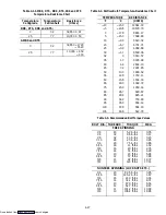
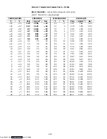
5. From the temperature/pressure chart (Table 4-6),
determine the saturation temperature corresponding to the
evaporator outlet pressure.
6. Note the temperature of the suction gas at the
expansion valve bulb.
7. Subtract the saturation temperature determined
in Step 6 from the average temperature measured in Step 5.
The difference is the superheat of the suction gas.
NOTE
Suction pressure must be 0.5 kg/cm
@
(6 psig) below
valve M.O.P. (maximum operating pressure).
Example:
if valve rated at 55 MOP, suction
pressure must be below this MOP. Recommended
pressure is below 3.44 kg/cm
@
(49 psig).
4.27 EVAPORATOR FAN MOTOR CAPACITORS
(OPTIONAL)
The
evaporator
fan
motors
are
of
the
permanent-split capacitor type. The motor is equipped
with one capacitor (used in the high speed circuit) and
another capacitor is used for the low speed circuit.
a. When to check for a defective capacitor
1. Fan motor will not change speed. For example:
controller settings above ---10
_
C (+14
_
F) should cause
the motor to run in high speed.
Controller settings below ---10
_
C (+14
_
F)
should cause the motor to run in low speed.
2. Motor running in wrong direction (after
checking for correct wiring application).
b. Removing the capacitor
WARNING
Make sure power to the unit is OFF and power
plug disconnected before removing capacitor(s).
1. The capacitor located on the motor and above
the evaporator fan deck may be removed by two methods:
(a)
If container is empty
, open upper, rear,
panel of the unit and capacitor may be serviced after
disconnecting power plug.
(b)
If container is full,
turn the unit power OFF
and disconnect power plug. Remove the evaporator fan
motor access panel. (See Figure 1-1). Remove two lower
capscrews securing motor assembly to bracket and then
remove Ty-Raps from wire harness. Loosen two upper
capscrews on the fan motor assembly. Remove or set
aside motor to reach capacitors.
WARNING
With power OFF discharge the capacitor and
disconnect the circuit wiring.
c. Checking the capacitor
Three methods for checking capacitors are:
(1) Direct replacement, (2) volt-ohmmeter, and (3)
capacitor analyzer.
1.
Direct replacement
of capacitor with one of the
same value.
2.
Volt-ohmmeter set on RX 10,000 ohms.
Connect
ohmmeter leads across the capacitor terminals and
observe the meter needle. If the capacitor is good, the
needle will make a rapid swing toward zero resistance and
then gradually swing back toward a very high resistance
reading.
If the capacitor has failed open, the ohmmeter
needle will not move when the meter probes touch the
terminals. If the capacitor is shorted, the needle will
swing to zero resistance position and stay there.
3.
Capacitor analyzer
The function of the analyzer is to read the
microfarad value of a capacitor and to detect insulation
breakdown under load conditions. The important
advantages of a analyzer is its ability to locate capacitors
that have failed to hold their microfarad ratings or ones
that are breaking down internally during operation. It is
also useful in identifying capacitors when their
microfarad rating marks have become unreadable.
Downloaded from

