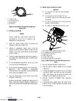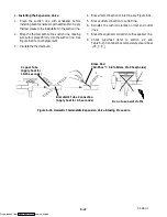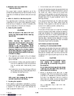
6-25
T-294-01
d. Checking the Drive Module
1. Turn unit OFF.
2. Disconnect the four pin connector to stepper SMV.
3. Attach the positive lead of a AC volt meter, and set
to read up to 24 volts to outlet pin “A” (1A) of the
four pin connector and the negative lead to the “B”
pin (1B).
4. Turn ON unit for 40 seconds, and watch the volt
meter. There should be approximately 9 to 12 volts
shown on the meter.
5. Repeat for pins “C” and “D” (pins 2 A and 2 B).
6. If only one set of pins reads a voltage, check
connections and retest.
7. If the retest reads out the same, the drive module or
controller is faulty.
8. If no voltage is present in any step, the output from
the controller to the drive module may be faulty,
and will require checking the connections and wires
from the controller to the drive module. Refer to
section 6.24.e.
9. To replace the drive module, disconnect all
connectors, unscrew from mounting, and replace
with a NEW drive module in reverse order.
e. Checking the Controller
1.
Turn the unit OFF.
2. Disconnect the six pin connector to the stepper
drive from the controller.
3. Attach the positive lead of a DC voltmeter set to
read up to 50 VDC to outlet pin “A” of the six pin
connector, and the negative lead to TP-9 of
controller or pin “B” (GD).
4. Turn ON the unit for 40 seconds, and watch the
voltmeter. There should be approximately 24 to 32
VDC shown on “A” pin (DC).
5. There should be zero volts on pin “B” (GD).
6. There should be approximately 24 to 32 VDC on
pin “E” (ON).
7. Pins “C” and “D” will have zero to 5 volts transistor
logic (TTL) signals present, however, this can only
be checked with the connector assembled as this is
an open collector type circuit.
By checking the outputs on “A,” “B,” and “E” it can be
verified that the controller is attempting to
communicate with the drive module. To be thorough,
and if it is desired, the TTL signals on pins “C” and “D”
can be checked as follows:
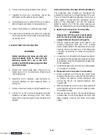
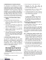
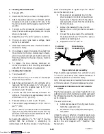
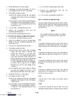
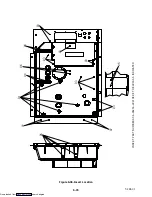
S
Make up a jumper assembly in which the
drive module and controller connectors can
be joined as in Figure 6-28 with the jumper
completing the circuits from the controller to
the drive module.
S
Remove the insulation from a one inch
section of wire, which join the two connector
halves.
S
Connect the positive lead of the voltmeter to
the bare section of wire “C” and “B,” and run
as before by resetting unit.
S
Repeat for wires “D” and “B.”
A
B
C
D
E
A
B
C
D
E
Controller
Connector (EC)
Drive Module
Connector (SD)
Jumper
Figure 6-28. Jumper Assembly
There should be approximately five volts DC on pins
“C” and “D” (S1 and S2) when measured as above. If
not the connections or controller is faulty.
If any of these pins are not consistent, the connections or
controller is suspect. Check and replace as required.
6.25 HERMETIC THERMOSTATIC EXPANSION
VALVE
The thermal expansion valve (see Figure 6-30) is an
automatic device which maintains constant superheat of
the refrigerant gas leaving the evaporator, regardless of
suction pressure.
The valve functions are:
S
Automatic response of the refrigerant flow to
match the evaporator load.
S
Prevention of liquid refrigerant entering the
compressor.
Unless the valve is defective, it seldom requires any
maintenance other than minor periodic maintenance to
insure that the thermal bulb is tightly secured to the
suction line and wrapped with “Presstite.” (See
Figure 6-29)
Downloaded from


