6-26
T-294-01
1
2
3
4
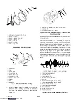
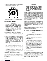
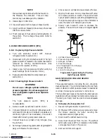
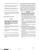
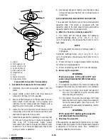
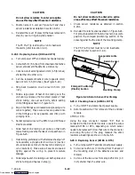
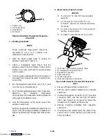
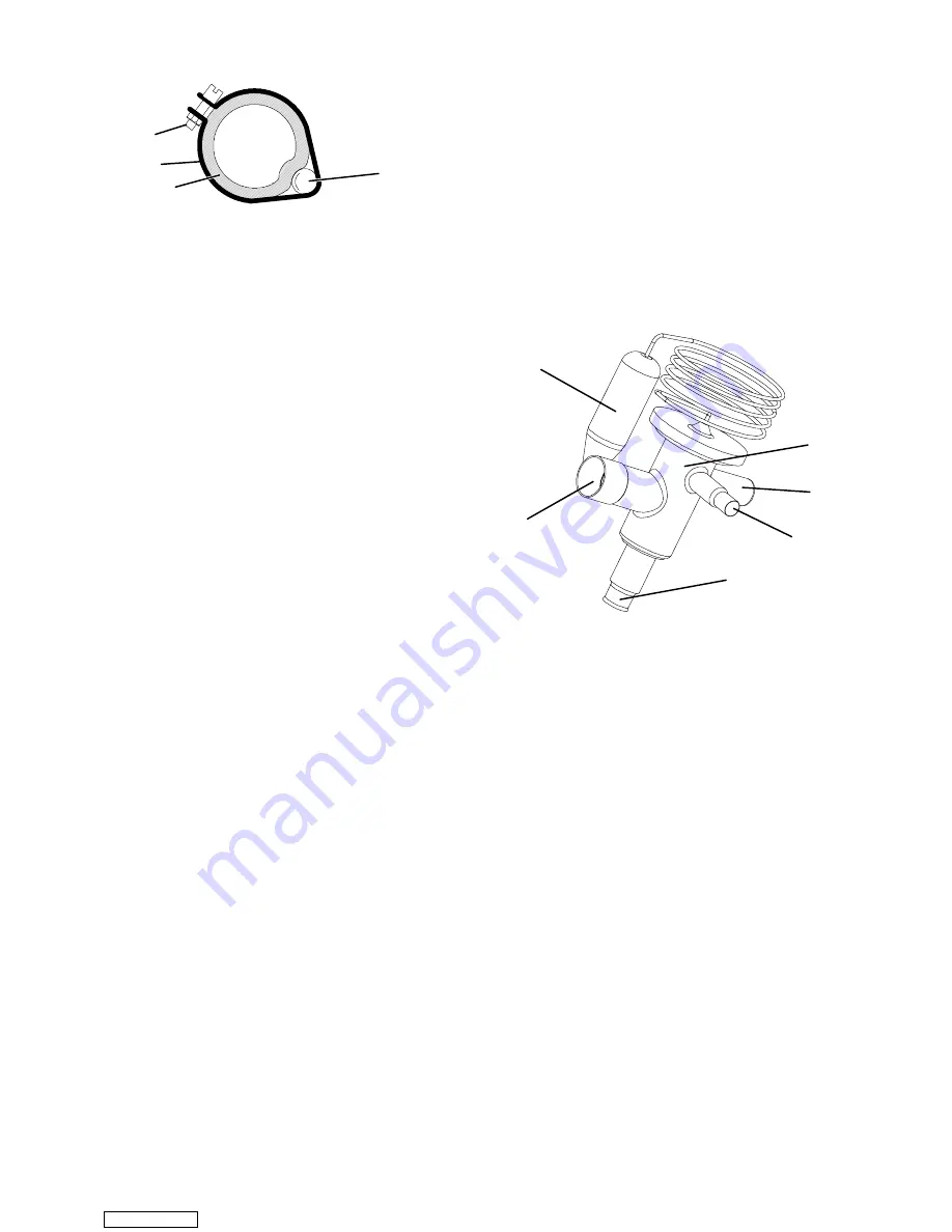
1. Suction Line
2. TXV Bulb Clamp
3. Nut and Bolt
4. TXV Bulb
Figure 6-29. Hermetic Thermostatic Expansion
Valve Bulb
a. Checking Superheat
NOTE
Proper superheat measurement should be
completed at --18
_
C (0
_
F) container box
temperature where possible.
1. Open the heater access panel to expose the
expansion valve (see Figure 2-1).
2. Attach a temperature tester sensor near the
expansion valve bulb and insulate. Make sure the
suction line is clean and that firm contact is made
with the sensor.
3. Connect an accurate gauge to the piercing valve on
the liquid line process tube (refer to sections 6.2,
6.3 and 6.4).
4. Set the temperature set point to --18
_
C (0
_
F), and
run unit until unit has stabilized.
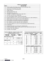
5. From the temperature/pressure chart (Table 6-9),
determine
the
saturation
temperature
corresponding to the evaporator outlet test pressure
at the suction modulation valve.
6. Note the temperature of the suction gas at the
expansion valve bulb.
Subtract the saturation temperature determined in
step 6. from the average temperature measured in
step 5. The difference is the superheat of the suction
gas.
b. Removing the Expansion Valve
NOTES
S
The hermetic TXV does NOT have adjustable
superheat.
S
All connections on the hermetic TXV are
bi--metallic, copper on the inside and stainless on
the outside.
S
All joints on the hermetic TXV (inlet, outlet and
equalizer lines) are brazed.
S
Bi--metallic connections heat up very quickly.
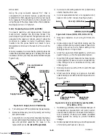
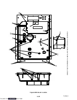
3
4
5
1
6
2
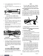
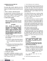
1. Hermetic Thermostatic Expansion Valve
2. Non-adjustable Superheat Stem
3. Equalizer Connection
4. Inlet Connection
5. Outlet Connection
6. Hermetic Expansion Valve Bulb
Figure 6-30. Hermetic Thermostatic Expansion
Valve
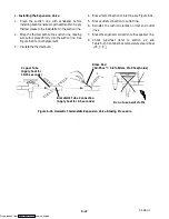
1. Recover refrigerant (refer to section 6.4).
2. Remove cushion clamps located on the inlet and
outlet lines.
3. Unbraze the equalizer connection (1/4”), the outlet
connection (5/8”) and then the inlet connection
(3/8”). See Figure 6-31. Be careful to protect the
insulation on the heaters and their wires.
4. Remove insulation (Presstite) from expansion
valve bulb.
5. Unstrap the bulb, located below the center of the
suction line (4 o’clock position), and remove the
valve (one strap.)
Downloaded from

