6-1
T-294-01
SECTION 6
SERVICE
NOTE
To avoid damage to the earth’s ozone layer, use a refrigerant recovery system whenever removing refrigerant.
When working with refrigerants you must comply with all local government environmental laws. In the
U.S.A., refer to EPA section 608.
6.1 REPAIRING THE REFRIGERATION SYSTEM
The unit is designed as a hermetic system, which
reduces the number of potential leak-points for
refrigerant. Therefore the suction service, discharge
service and manual liquid line valves have been
eliminated in comparison to the standard container unit.
In conjunction, the sight glass on the water-cooled
condenser, and the filter-drier quick--connect nuts have
also been removed. These areas have either been
completely eliminated, or have been replaced with
brazed joints.
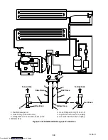
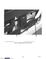
To perform maintenance on the system, two process
tubes have been provided, which are the liquid line and
suction line process tubes, see Figure 6-4 for locations.
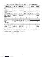
Refer to Table 6-4 for a list of the tools required to
perform the tasks in sections 6.2, 6.3 and 6.4.
6.2 PIERCING VALVES
To gain access to the hermetic system, it is
recommended to use the Robinair P/N 40288 piercing
valve on the units process tubes.
a. Preparation
1. Tubing should be straight and round.
2. Carefully clean the process tubing where the
piercing valve will be attached, do NOT scratch the
tubing.
3. Make sure there are no dents in the tubing.
4. Apply a little clean refrigerant oil to the tubing
where the piercing valve will be placed.
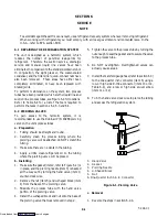
b. Installing
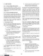
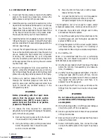
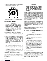
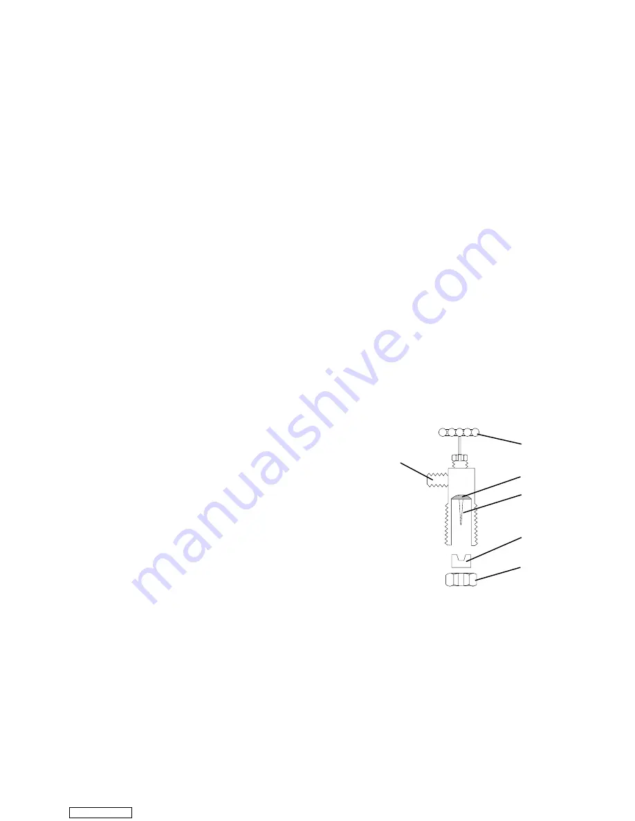
1. Make sure the gasket (item 2, refer to Figure 6-1) is
in place, and the piercing needle (item 3) is backed
all the way out by turning the hand valve (item 1)
counter-clockwise.
2. Remove the nut (item 5) and u-shaped block (item
4) from the base of the piercing valve.
3. Straddle the process tube with the hand valve
portion of the piercing valve.
4. Install the u-shaped block and nut onto the base of
the piercing valve that was removed in step 2.
5. Tighten the valve to the process tube by turning the
nut enough to seal the gasket and to secure the valve
to the process tube.
6. Do NOT overtighten. Overtightened valves can
actually cause a leak.
7. Install the manifold gauge hose (refer to section 6.3)
to the one-quarter inch connector (item 6) using a
low or high side R-134a connector (item 13 or 14,
Table 6-4), and a low or high side swivel elbow
(item 11 or 12).
8. Turn the hand valve clockwise to pierce the tubing
and access the refrigeration system.
1
2
3
4
5
6
1. Hand Valve
2. Gasket
3. Piercing Needle
4. U-Shaped Block
5. Nut
6. One-Quarter Inch S.A.E. Connector
Figure 6-1. Piercing Valve
c. Removal
1. Reverse the steps in section 6.2.b.
Downloaded from

