6-20
T-294-01
6.20 MAINTENANCE OF PAINTED SURFACES
The refrigeration unit is protected by a special paint
system against the corrosive atmosphere in which it
normally operates. However, should the paint system be
damaged, the base metal can corrode. In order to protect
the refrigeration unit from the highly corrosive sea
atmosphere, or if the protective paint system is
scratched or damaged, clean area to bare metal using a
wire brush, emery paper or equivalent cleaning method.
Immediately following cleaning, spray or brush on
zinc-rich primer. After the primer has dried, spray or
brush on finish coat of paint to match original unit color.
6.21 POWER AUTOTRANSFORMER (TRANS) --
Optional
If the unit does not start, check the following:
a. Make sure the 460 vac (yellow) power cable is
plugged into the receptacle (item 3, Figure 2-7) and
locked in place.
b. Make sure that circuit breakers CB-1 and CB-2 are
in the “ON” position. If the circuit breakers do not
hold in, check voltage supply.
c. There is no internal protector for this particular
transformer design, therefore, no checking of the
internal protector is required.
d. Using a voltmeter, and with the primary supply
circuit ON, check the primary (input) voltage (460
vac). Next, check the secondary (output) voltage
(230 vac). The transformer is defective if voltage is
not available.
6.22 TRANSFORMER BRIDGING UNIT (TBU)
The transformer bridging unit (TBU) will reduce
attenuation (i.e., loss of signal power in a transmission)
that occurs when a high frequency remote monitoring
unit
(RMU)
signal
is
passed
through
an
autotransformer. The TBU allows high frequency
remote monitoring signals to effectively bypass the
460/230 vac autotransformer (TRANS).
WARNING
Before servicing unit, make sure the unit
circuit breakers (CB-1 & CB-2) and the
start-stop switch (ST) are in the OFF
position, and that the power plug and cable
are disconnected.
If the device does not appear to be functioning, check
the following:
a. Make sure power to the unit is OFF.
b. Refer to Figure 2-7 for the location of TBU.
c. Disconnect
the
TBU
from
across
the
autotransformer. This will isolate the device and
allow for accurate measurements.
d. Using a capacitor meter (i.e., Fluke 87), measure
between L1 and L1, L2 and L2, L3 and L3.
e. The readings should be 0.44
µ
F, plus or minus 14%.
f. If the readings do NOT fall in the above described
range, the device must be replaced.
NOTE
An ohmmeter may be used as a cross check for
shorted capacitors in the TBU. However, it will
NOT accurately check for an open capacitor; as
the ohmmeter will read open for both good or
open capacitors.
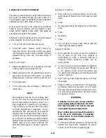
6.23 SENSOR CHECKOUT PROCEDURE (AMBS,
DTS, RRS, RTS, SRS & STS)
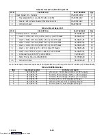
An accurate ohmmeter must be used to check the
resistance values shown in Table 6-5.
Due to the variations and inaccuracies in ohmmeters,
thermometers or other test equipment, a reading within
2% of the chart value would indicate a good sensor. If a
sensor is defective, the resistance reading will usually
be much higher or lower than the resistance values given
in Table 6-5.
6.23.1 Checking Sensor (RRS, RTS, SRS or STS)
a. Place the sensor (sensing bulb) in a 0
_
C (32
_
F)
ice-water bath. The ice-water bath is prepared by
filling an insulated container (of sufficient size to
completely immerse bulb) with ice cubes or
chipped ice, then filling voids between ice with
water and agitating until mixture reaches 0
_
C
(32
_
F) measured on a laboratory thermometer.
b. Start unit and check air temperature/data readout on
the control panel. The reading should be 0
_
C
(32
_
F); if it is not, continue on to the following step.
c. Turn unit OFF and disconnect power supply.
d. Refer to section 6.27 for removal of the Controller
module.
RTS or STS:
Using the plug connector marked “EC” that is
connected to the Controller module. Locate the wires
marked RTS or STS, depending on which sensor needs
to be replaced. Follow that wire to the connector and
using the pins of the plug, measure the ohms resistance.
Readings are shown in Table 6-5.
Downloaded from


