6-23
T-294-01
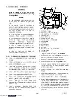
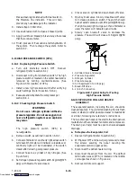
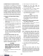
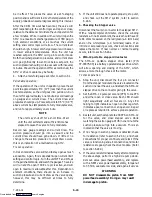
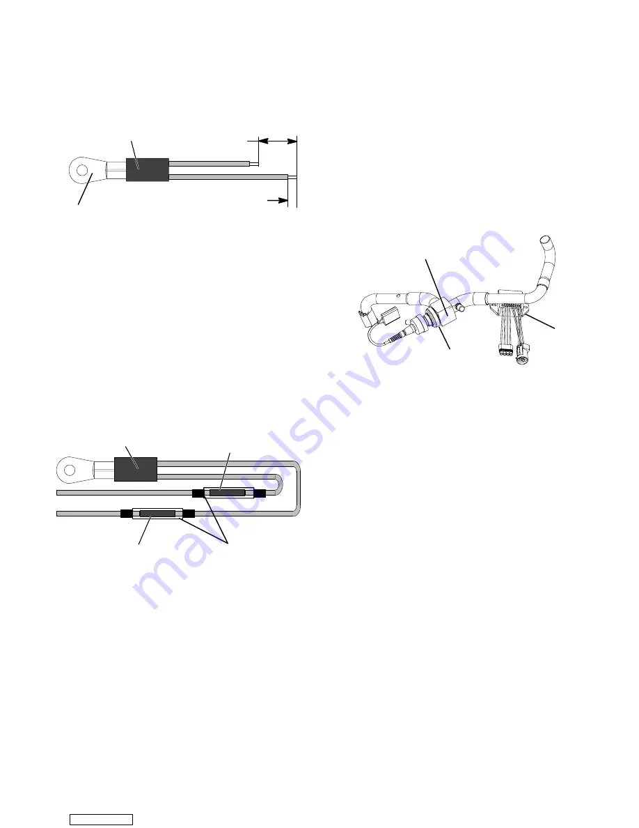
d. Cut one replacement sensor wire back 25.4 mm (1.0
inch). (See Figure 6-25.)
e. Strip back insulation on all wiring 6.35mm (1/4
inch).
Sensor
25.4 mm (1.0 inch)
6.35mm (1/4 inch)
Mounting Stud
Figure 6-25. Sensor (AMBS or DTS)
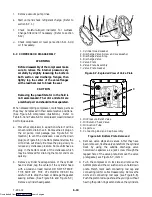
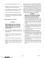
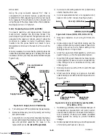
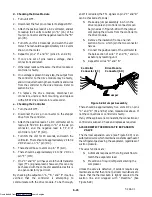
f. Slide two small pieces of heat shrink tubing over
each wire before adding crimp fittings as shown in
Figure 6-26.
g. Slip crimp fittings over dressed wires. Make sure
wires are pushed into crimp fittings as far as
possible and crimp with crimping tool.
h. Solder spliced wires with a 60% tin and 40% lead
Rosincore solder.
i. Slide heat shrink tubing over splice so that both
ends of tubing cover both ends of crimp as shown in
Figure 6-26.
Sensor
Heat Shrink
Tubing (2)
Crimp Fitting
Crimp Fitting
Figure 6-26. Sensor and Wire Assembly (AMBS or
DTS)
j. Heat tubing, preferably with a flameless heat gun. If
not available, a propane torch will work
(caution
should be taken not to burn the heat shrink tubing or
wire insulation
). Make sure all seams are sealed
tightly against the wiring to prevent moisture
seepage.
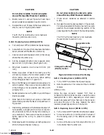
CAUTION
Do not allow moisture to enter wire splice
area as this may affect the sensor resistance.
k. Secure sensor to unit and check sensor resistance as
detailed in section 6.23.4.
NOTE
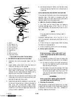
The DTS sensor must have “Presstite”
insulating material placed completely over the
sensor to insure proper function of the sensor.
6.24 STEPPER MOTOR SUCTION MODULATION
VALVE (SMV)
On start up of the unit, the valve will reset to a known
open position. This is accomplished by assuming the
valve was fully open, driving it fully closed, resetting
the percentage open to zero, then opening to a known
21% staging position. This makes the unit ready to start
and normal operation will begin.
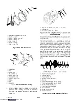
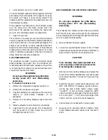
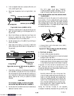
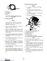
2-1/8 inch Nut
2
1
1. Stepper Motor Suction Modulation Valve (SMV)
2. Drive Module (SD)
Figure 6-27. Stepper Motor Suction Modulation
Valve (SMV)
a. Pre-Check procedure
1. Check unit for abnormal operation.
2. Check charge. If refrigerant is low repair as required
and again check operation.
3. If sufficient capacity cannot be maintained or unit is
tripping excessively on high pressure switch (HPS)
in high ambients, check coil and clean if required.
If capacity or control cannot be maintained turn unit
OFF, then back ON. This will reset the valve in the
event the controller lost communication with the valve,
and may correct the problem.
NOTE
Carefully listen to the valve. During reset, the
valve will make a ratcheting noise that may be
heard or felt (this depends upon background
noise) as it is attempting to close. If this can be
heard or felt, it indicates that the controller and
drive module are attempting to close the valve,
and may serve as a quick indication that the
drive module is in working order.
During the first few minutes of unit operation,
compressor reliability enhancement logic (CREL) may
Downloaded from

