6-29
T-292
Materials needed:
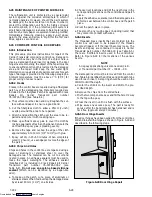
1. Cut two square pieces of 3 mm thick (1/8 inch) alumi-
num or stainless steel approximately 40 mm (1 5/8”)
square. These squares will serve as backing plates.
2. Two nuts, bolts (10 -- 24 x 1”) and washers for each
insert that needs repair.
a. Drill a 1/4” hole in the center of each square backing
plate.
b. Pass the bolts through the bolts holes in the door
hinge, then through the control box at the location
where the hinge insert pulled out.
c. From inside the control box, slide the backing plates
over the bolts and secure in place with the washers
and nuts.
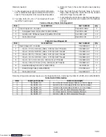
Table 6-4 Crack, Chip & Hole Repair Kit
ITEM
DESCRIPTION
PART NUMBER
Qty
1
Crack Repair Kit -- Includes
76--00724--00SV
1
2
Fiberglass Patch Kit (Loctite FK--98 or 80265)
. . .
76--00724--00Z
10
3
Sikaflex 221 Adhesive Sealant (Sikaflex 232--361)
. . .
02--00067--02Z
10
4
Instruction Sheet
. . .
98--02339--00
10
Table 6-5 Insert Repair Kit
ITEM
DESCRIPTION
PART NUMBER
Qty
1
Insert Repair Kit -- Includes
76--50084--00
1
2
Insert - 17.53 x 9.91 mm (.690 x .390 in) 1/4--20 Threads
. . .
34--06231--01
10
3
Insert - 15.88 x 6.35 mm (.625 x .250 in) 10-24 Threads
. . .
34--06231--03
10
4
Insert - 25.15 x 7.54 mm (.990 x .297 in) 10-24 Threads
. . .
34--06231--04
10
5
Insert - 10.16 x 9.53 mm (.400 x .375 in) 10-24 Threads
. . .
34--06231--05
10
6
Insert - 12.7 x 9.91 mm (.5 x .390 in) 1/4--20 Threads
. . .
34--06231--06
10
7
Insert - 9.53 x 6.76 mm (.375 x .266 in) 10-24 Threads
. . .
34--06231--07
10
8
Durabond Epoxy E20--HP (Loctite 29314)
. . .
02--0082--00
1
9
Static Mixing Tube (Loctite 983440)
. . .
07--00390--00
1
10
Instruction Sheet
. . .
98--02338--00
1
Note: Insert repair procedures require use of an Application Gun, Carrier part number 07--00391--00 (Loctite 983435)
Table 6-6 Drill Information
Item
Insert part number
Drill size and depth
1
34- 06231- 01
10.3 mm x 17.8 mm deep (.404 in. x .700 in. deep)
2
34- 06231- 03
6.8 mm x 16.3 mm deep (.266 in. x .640 in. deep)
3
34- 06231- 04
7.9 mm x 25.4 mm deep (.3125 in. x 1.0 in. deep)
4
34- 06231- 05
6.9 mm (.270 in.) Drill completely through.
5
34- 06231- 06
10.3 mm (.404 in.) Drill completely through.
6
34- 06231- 07
6.8 mm (.266 in.) Drill completely through.
Downloaded from
Summary of Contents for 69NT40-531 Series
Page 2: ...Downloaded from ManualsNet com search engine ...
Page 4: ...Downloaded from ManualsNet com search engine ...
Page 8: ...Downloaded from ManualsNet com search engine ...
Page 16: ...Downloaded from ManualsNet com search engine ...
Page 57: ...Downloaded from ManualsNet com search engine ...
Page 104: ...Downloaded from ManualsNet com search engine ...
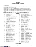
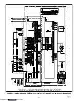
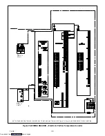
Page 106: ...7 2 T 292 Figure 7 2 SCHEMATIC DIAGRAM Downloaded from ManualsNet com search engine ...

