Index-1
T-292
INDEX
A
Air Cooled Condenser Section, 2-4
Alarm, 3-6, 3-10, 3-11, 3-12, 3-16, 3-26
Autotransformer, 1-2, 6-19
B
Battery, 1-1
C
Capacitors, 6-17
Checking Superheat, 6-13
Communications, 1-1
Communications Interface Module, 3-11, 6-31
Compressor, 1-1, 6-7
Compressor Phase Sequence, 4-6
Compressor Section, 2-3
Condenser Coil, 1-2, 6-10
Condenser Fan, 6-10
Configuration Identification, 1-1
Configuration Software, 3-4, 3-8
Configuration Variables, 3-12
Control Box, 1-1, 6-28
Controlled Atmosphere, 1-2
Controller, 3-3, 6-19
Controller Software, 3-3
D
DataCORDER, 3-7, 3-10, 4-3
DataCORDER Software, 3-7
DataReader, 3-10
DataView, 3-11
Defrost Interval, 3-4
Defrost Mode, 4-7
Dehumidification, 1-1
Display Module, 3-2
E
Emergency Bypass, 4-9
Emergency Defrost, 4-9
Evacuation, 6-3, 6-6
Evaporator, 6-15
Evaporator Fan, 1-2, 6-16
Evaporator Section, 2-2
Expansion Module, 3-1, 6-19
Expansion Valves, 6-13
F
Failure Action, 3-4
Filter--Drier, 6-13
Fresh Air Makeup, 2-1, 4-1
Frozen Mode, 4-7
Frozen Mode -- Conventional, 3-6
Frozen Mode -- Economy, 3-6
Function Code, 3-13, 3-24
G
General Description, 2-1
Generator Protection, 3-4
Gutters, 1-2
H
Handles, 1-2
Heat Lockout, 3-4, 3-6
Heater, 6-15
Heating Mode, 4-7
High Pressure Switch, 6-9
I
Inspection, 4-1, 4-3
Interrogator, 1-1
Introduction, 1-1
K
Key Pad, 3-2
Downloaded from
Summary of Contents for 69NT40-531 Series
Page 2: ...Downloaded from ManualsNet com search engine ...
Page 4: ...Downloaded from ManualsNet com search engine ...
Page 8: ...Downloaded from ManualsNet com search engine ...
Page 16: ...Downloaded from ManualsNet com search engine ...
Page 57: ...Downloaded from ManualsNet com search engine ...
Page 104: ...Downloaded from ManualsNet com search engine ...
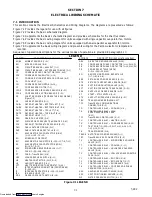
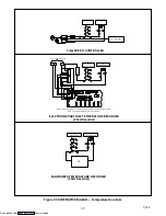
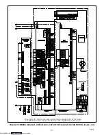
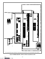
Page 106: ...7 2 T 292 Figure 7 2 SCHEMATIC DIAGRAM Downloaded from ManualsNet com search engine ...

