Index-2
T-292
L
Logging Interval, 3-10
Lower Air, 1-2
M
Manifold Gauge Set, 6-1
Microporcessor System, 3-1
Modes Of Operation, 3-4
O
Oil, 6-9
Operational Software, 3-4, 3-7
Option Descriptions, 1-1
P
Painted Surfaces, 6-28
Perishable Mode -- Bulb, 3-5
Perishable Mode -- Conventional, 3-4
Perishable Mode -- Dehumidification, 3-5
Perishable Mode -- Economy, 3-5
Power, 4-1
Pre--Trip, 3-7, 3-10, 3-20, 3-25, 4-3
Pressure Readout, 1-1
Probe Check, 4-4
Pumping Down, 6-2
R
Refrigerant Charge, 6-4, 6-7
Refrigeration Circuit, 2-10
Refrigeration System Data, 2-7
Refrigeration Unit -- Front Section, 2-1
Remote Monitoring, 1-1
S
Safety and Protective Devices, 2-9
Sampling Type, 3-10
Sensor Configuration, 3-8
Sequence Of Operation, 4-5
Service Valves, iv, 6-5
Solenoid Valves, 6-15
Starting, 4-3
Stopping, 4-3
Suction Modulating Valve, 6-18
T
Temperature Control, 3-4, 3-6
Temperature Readout, 1-1
Temperature Recorder, 1-2, 4-3, 6-22, 6-24, 6-26
Temperature Sensor, 6-21
Thermistor Format, 3-10
Thermometer Port, 1-2
Torque Values, 6-31
U
Upper Air, 1-2
USDA, 1-1, 3-11
V
Valve Override Controls, 6-17
W
Water Cooled Condenser, 6-11
Water Cooling, 1-2
Water--Cooled Condenser Section, 2-5
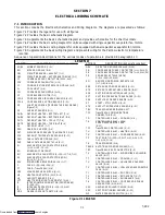
Wiring Schematic, 7-1
Downloaded from
Summary of Contents for 69NT40-531 Series
Page 2: ...Downloaded from ManualsNet com search engine ...
Page 4: ...Downloaded from ManualsNet com search engine ...
Page 8: ...Downloaded from ManualsNet com search engine ...
Page 16: ...Downloaded from ManualsNet com search engine ...
Page 57: ...Downloaded from ManualsNet com search engine ...
Page 104: ...Downloaded from ManualsNet com search engine ...
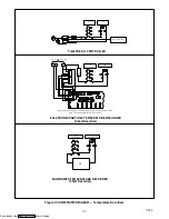
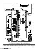
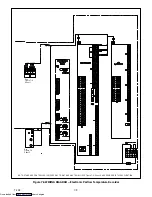
Page 106: ...7 2 T 292 Figure 7 2 SCHEMATIC DIAGRAM Downloaded from ManualsNet com search engine ...

