background image

vii

T--292

LIST OF ILLUSTRATIONS -- Continued

FIGURE NUMBER

Page

Figure 6-11 Water Cooled Condenser Cleaning - Gravity Circulation

6-12

. . . . . . . . . . . . . . . . . . . . . . . . . . . . . . . . .

Figure 6-12 Thermostatic Expansion Valve Bulb

6-13

. . . . . . . . . . . . . . . . . . . . . . . . . . . . . . . . . . . . . . . . . . . . . . . . . .

Figure 6-13 Hermetic Thermostatic Expansion Valve Brazing Procedure

6-14

. . . . . . . . . . . . . . . . . . . . . . . . . . . . .

Figure 6-14 Evaporator Expansion Valve

6-14

. . . . . . . . . . . . . . . . . . . . . . . . . . . . . . . . . . . . . . . . . . . . . . . . . . . . . . . .

Figure 6-15 Quench & Economizer Expansion Valves

6-14

. . . . . . . . . . . . . . . . . . . . . . . . . . . . . . . . . . . . . . . . . . . . .

Figure 6-16. Unloader Solenoid Valve

6-16

. . . . . . . . . . . . . . . . . . . . . . . . . . . . . . . . . . . . . . . . . . . . . . . . . . . . . . . . . . .

Figure 6-17. Oil Return Solenoid Valve (ORV) and Economizer Solenoid Valve (ESV)

6-16

. . . . . . . . . . . . . . . . . .

Figure 6-18. Evaporator Fan Assembly

6-17

. . . . . . . . . . . . . . . . . . . . . . . . . . . . . . . . . . . . . . . . . . . . . . . . . . . . . . . . . .

Figure 6-19 Suction Modulation Valve (SMV)

6-18

. . . . . . . . . . . . . . . . . . . . . . . . . . . . . . . . . . . . . . . . . . . . . . . . . . . . .

Figure 6-20 Controller Section of the Control Box

6-19

. . . . . . . . . . . . . . . . . . . . . . . . . . . . . . . . . . . . . . . . . . . . . . . . .

Figure 6-21 Sensor Types

6-21

. . . . . . . . . . . . . . . . . . . . . . . . . . . . . . . . . . . . . . . . . . . . . . . . . . . . . . . . . . . . . . . . . . . . .

Figure 6-22 Sensor and Cable Splice

6-21

. . . . . . . . . . . . . . . . . . . . . . . . . . . . . . . . . . . . . . . . . . . . . . . . . . . . . . . . . . .

Figure 6-23 Supply Sensor Positioning

6-22

. . . . . . . . . . . . . . . . . . . . . . . . . . . . . . . . . . . . . . . . . . . . . . . . . . . . . . . . . .

Figure 6-24 Return Sensor Positioning

6-22

. . . . . . . . . . . . . . . . . . . . . . . . . . . . . . . . . . . . . . . . . . . . . . . . . . . . . . . . . .

Figure 6-25. Electronic Partlow Temperature Recorder

6-23

. . . . . . . . . . . . . . . . . . . . . . . . . . . . . . . . . . . . . . . . . . . .

Figure 6-26. Partlow Mechanical Temperature Recorder

6-26

. . . . . . . . . . . . . . . . . . . . . . . . . . . . . . . . . . . . . . . . . . .

Figure 6-27. Saginomiya Temperature Recorder

6-27

. . . . . . . . . . . . . . . . . . . . . . . . . . . . . . . . . . . . . . . . . . . . . . . . . .

Figure 6-28 Door Hinge Repair

6-28

. . . . . . . . . . . . . . . . . . . . . . . . . . . . . . . . . . . . . . . . . . . . . . . . . . . . . . . . . . . . . . . . .

Figure 6-29. Insert Location

6-30

. . . . . . . . . . . . . . . . . . . . . . . . . . . . . . . . . . . . . . . . . . . . . . . . . . . . . . . . . . . . . . . . . . . .

Figure 6-30. Communications Interface Installation

6-31

. . . . . . . . . . . . . . . . . . . . . . . . . . . . . . . . . . . . . . . . . . . . . . . .

Figure 7-1 LEGEND

7-1

. . . . . . . . . . . . . . . . . . . . . . . . . . . . . . . . . . . . . . . . . . . . . . . . . . . . . . . . . . . . . . . . . . . . . . . . . .

Figure 7-2 SCHEMATIC DIAGRAM

7-2

. . . . . . . . . . . . . . . . . . . . . . . . . . . . . . . . . . . . . . . . . . . . . . . . . . . . . . . . . . . . .

Figure 7-3 SCHEMATIC DIAGRAM -- Temperature Recorders

7-3

. . . . . . . . . . . . . . . . . . . . . . . . . . . . . . . . . . . . .

Figure 7-4 WIRING DIAGRAM, UNITS W/SINGLE CAPACITOR EVAPORATOR FAN MOTORS

7-4

. . . . . . .

Figure 7-5 WIRING DIAGRAM , UNITS W/DUAL CAPACITOR EVAPORATOR FAN MOTORS

7-6

. . . . . . . . .

Figure 7-6 WIRING DIAGRAM -- Electronic Partlow Temperature Recorder

7-8

. . . . . . . . . . . . . . . . . . . . . . . . . .

LIST OF TABLES

TABLE NUMBER

Page

Table 2-1 Safety and Protective Devices

2-9

. . . . . . . . . . . . . . . . . . . . . . . . . . . . . . . . . . . . . . . . . . . . . . . . . . . . . . . . . .

Table 3-1 Key Pad Function

3-2

. . . . . . . . . . . . . . . . . . . . . . . . . . . . . . . . . . . . . . . . . . . . . . . . . . . . . . . . . . . . . . . . . . . . .

Table 3-2 DataCORDER Configuration Variables

3-8

. . . . . . . . . . . . . . . . . . . . . . . . . . . . . . . . . . . . . . . . . . . . . . . . . .

Table 3-3 DataCORDER Standard Configurations

3-8

. . . . . . . . . . . . . . . . . . . . . . . . . . . . . . . . . . . . . . . . . . . . . . . . . .

Table 3-4 Controller Configuration Variables

3-13

. . . . . . . . . . . . . . . . . . . . . . . . . . . . . . . . . . . . . . . . . . . . . . . . . . . . . . .

Table 3-5 Controller Function Codes

3-14

. . . . . . . . . . . . . . . . . . . . . . . . . . . . . . . . . . . . . . . . . . . . . . . . . . . . . . . . . . . . .

Table 3-6 Controller Alarm Indications

3-17

. . . . . . . . . . . . . . . . . . . . . . . . . . . . . . . . . . . . . . . . . . . . . . . . . . . . . . . . . . . .

Table 3-7 Controller Pre-Trip Test Codes

3-21

. . . . . . . . . . . . . . . . . . . . . . . . . . . . . . . . . . . . . . . . . . . . . . . . . . . . . . . . . .

Table 3-8 DataCORDER Function Code Assignments

3-25

. . . . . . . . . . . . . . . . . . . . . . . . . . . . . . . . . . . . . . . . . . . . . .

Table 3-9 DataCORDER Pre-Trip Result Records

3-26

. . . . . . . . . . . . . . . . . . . . . . . . . . . . . . . . . . . . . . . . . . . . . . . . . .

Table 3-10 DataCORDER Alarm Indications

3-27

. . . . . . . . . . . . . . . . . . . . . . . . . . . . . . . . . . . . . . . . . . . . . . . . . . . . . . .

Table 6-1 Compressor Kit

6-7

. . . . . . . . . . . . . . . . . . . . . . . . . . . . . . . . . . . . . . . . . . . . . . . . . . . . . . . . . . . . . . . . . . . . . . .

Table 6-2 Sensor Temperature/Resistance Chart (+/--.002%)

6-21

. . . . . . . . . . . . . . . . . . . . . . . . . . . . . . . . . . . . . . . .

Table 6-3 Temperature-Resistance Chart

6-26

. . . . . . . . . . . . . . . . . . . . . . . . . . . . . . . . . . . . . . . . . . . . . . . . . . . . . . . . .

Table 6-4 Crack, Chip & Hole Repair Kit

6-30

. . . . . . . . . . . . . . . . . . . . . . . . . . . . . . . . . . . . . . . . . . . . . . . . . . . . . . . . . .

Table 6-5 Insert Repair Kit

6-30

. . . . . . . . . . . . . . . . . . . . . . . . . . . . . . . . . . . . . . . . . . . . . . . . . . . . . . . . . . . . . . . . . . . . . .

Table 6-6 Drill Information

6-30

. . . . . . . . . . . . . . . . . . . . . . . . . . . . . . . . . . . . . . . . . . . . . . . . . . . . . . . . . . . . . . . . . . . . . .

Table 6-7 Recommended Bolt Torque Values

6-32

. . . . . . . . . . . . . . . . . . . . . . . . . . . . . . . . . . . . . . . . . . . . . . . . . . . . . .

Table 6-8 R-134a Temperature - Pressure Chart

6-33

. . . . . . . . . . . . . . . . . . . . . . . . . . . . . . . . . . . . . . . . . . . . . . . . . . .

Downloaded from 

ManualsNet.com

 search engine

Summary of Contents for 69NT40-531 Series

Page 1: ...T 292 Rev C Change 03 05 Carrier Transicold Container Refrigeration Operation Service Models 69NT40 531 001 to 199 Downloaded from ManualsNet com search engine ...

Page 2: ...Downloaded from ManualsNet com search engine ...

Page 3: ...1 to 199 Carrier Transicold A member of the United Technologies Corporation family Stock symbol UTX Carrier Transicold Divsion Carrier Corporation P O Box 4805 Syracuse N Y 13221 U S A ã 2003 CarrierCorporation D Printed in U S A 04 03 Downloaded from ManualsNet com search engine ...

Page 4: ...Downloaded from ManualsNet com search engine ...

Page 5: ...fety devices e g bridging an overload or using any sort of jumper wires Problems with the system should be diagnosed and any necessary repairs performed by qualified service personnel When performing any arc welding on the unit or container disconnect all wire harness connectors from the modules in both control boxes Do not remove wire harness from the modules unless you are grounded to the unit f...

Page 6: ...WARNING Always turn OFF the unit circuit breakers CB 1 CB 2 and disconnect main power supply before working on moving parts WARNING Make sure power to the unit is OFF and power plug disconnected before removing capacitor s WARNING With power OFF discharge the capacitor before disconnecting the circuit wiring WARNING Do not use a nitrogen cylinder without a pressure regulator Do not use oxygen in o...

Page 7: ...Oil POE Castrol Icematic SW20 compressor oil with R 134a Buy in quantities of one quart or smaller When using this hygroscopic oil immediately reseal Do not leave container of oil open or contamination will occur CAUTION Take necessary steps place plywood over coil or use sling on motor to prevent motor from falling into condenser coil CAUTION DO NOT disassemble piston from NEW suction modulating ...

Page 8: ...Downloaded from ManualsNet com search engine ...

Page 9: ...ndenser Coil 1 1 1 3 12 Autotransformer 1 2 1 3 13 Temperature Recorder 1 2 1 3 14 Gutters 1 2 1 3 15 Handles 1 2 1 3 16 Thermometer Port 1 2 1 3 17 Water Cooling 1 2 1 3 18 Back Panels 1 2 1 3 19 460 Volt Cable 1 2 1 3 20 230 Volt Cable 1 2 1 3 21 Cable Restraint 1 2 1 3 22 Upper Air Fresh Air Make Up 1 2 1 3 23 Lower Air Fresh Air Make Up 1 2 1 3 24 Controlled Atmosphere 1 2 1 3 25 Power Correct...

Page 10: ...es 3 3 3 2 2 Operational Software Function codes 3 4 3 3 MODES OF OPERATION 3 4 3 3 1 Temperature Control Perishable Mode 3 4 3 3 2 Defrost Interval 3 4 3 3 3 Failure Action 3 4 3 3 4 Generator Protection 3 4 3 3 5 Compressor High Temperature Low Pressure Protection 3 4 3 3 6 Perishable Mode Conventional 3 4 3 3 7 Perishable Mode Economy 3 5 3 3 8 Perishable Mode Dehumidification 3 5 3 3 9 Perisha...

Page 11: ... 4 2 Water Cooled Condenser with Condenser Fan Switch 4 2 4 5 CONNECT REMOTE MONITORING RECEPTACLE 4 3 4 6 STARTING AND STOPPING INSTRUCTIONS 4 3 4 6 1 Starting the Unit 4 3 4 6 2 Stopping the Unit 4 3 4 7 START UP INSPECTION 4 3 4 7 1 Physical Inspection 4 3 4 7 2 Check Controller Function Codes 4 3 4 7 3 Start Temperature Recorder 4 3 4 7 4 Complete Inspection 4 3 4 8 PRE TRIP DIAGNOSIS 4 3 4 9 ...

Page 12: ... 6 1 6 2 MANIFOLD GAUGE SET 6 1 6 3 REFRIGERATION SYSTEM SERVICE UNITS WITH STANDARD PIPING with Service Valves 6 2 6 3 1 Service Connections 6 2 6 3 2 Pumping Down the Unit 6 2 6 3 3 Refrigerant Leak Checking 6 3 6 3 4 Evacuation and Dehydration 6 3 6 3 5 Refrigerant Charge 6 4 6 4 REFRIGERATION SYSTEM SERVICE UNITS WITH SEMI HERMETIC PIPING without Service Valves 6 4 6 4 1 Service Connections 6 ...

Page 13: ...1 When To Check For A Defective Capacitor 6 17 6 16 2 Removing The Capacitor 6 17 6 16 3 Checking The Capacitor 6 17 6 17 VALVE OVERRIDE CONTROLS 6 17 6 18 SUCTION MODULATION VALVE 6 18 6 18 1 Precheck Procedure 6 18 6 18 2 Checking The Stepper valve 6 18 6 19 AUTOTRANSFORMER 6 19 6 20 CONTROLLER AND EXPANSION MODULE 6 19 6 20 1 Handling Modules 6 19 6 20 2 Controller Trouble Shooting 6 20 6 20 3 ...

Page 14: ...l System 3 1 Figure 3 2 Key Pad 3 2 Figure 3 3 Display Module 3 2 Figure 3 4 Control and Expansion Modules 3 3 Figure 3 5 Standard Configuration Download Report 3 9 Figure 3 6 Data Reader 3 10 Figure 4 1 Autotransformer 4 1 Figure 4 2 Make Up Air Flow Chart 4 2 Figure 4 3 Controller Operation Perishable Mode 4 5 Figure 4 4 Controller Operation Frozen Mode 4 6 Figure 4 5 Perishable Mode 4 6 Figure ...

Page 15: ...ion 6 31 Figure 7 1 LEGEND 7 1 Figure 7 2 SCHEMATIC DIAGRAM 7 2 Figure 7 3 SCHEMATIC DIAGRAM Temperature Recorders 7 3 Figure 7 4 WIRING DIAGRAM UNITS W SINGLE CAPACITOR EVAPORATOR FAN MOTORS 7 4 Figure 7 5 WIRING DIAGRAM UNITS W DUAL CAPACITOR EVAPORATOR FAN MOTORS 7 6 Figure 7 6 WIRING DIAGRAM Electronic Partlow Temperature Recorder 7 8 LIST OF TABLES TABLE NUMBER Page Table 2 1 Safety and Prote...

Page 16: ...Downloaded from ManualsNet com search engine ...

Page 17: ...m 1 3 OPTION DESCRIPTIONS Various options may be factory or field fitted to the base unit Brief descriptions of the options are provided in the following subparagraphs 1 3 1 Battery The controller may be fitted with standard replaceable batteries or a rechargeable battery pack 1 3 2 Dehumidification The unit may be fitted with a humidity sensor This sensor allows setting of a humidity set point in...

Page 18: ...hat may be fitted include panels of aluminum and stainless steel Panels may be fitted with access doors and or hinge mounting 1 3 19 460 Volt Cable Various power cable and plug designs are available for the main 460 volt supply The plug options tailor the cables to each customers requirements 1 3 20 230 Volt Cable Units equipped with an autotransformer require an additional power cable for connect...

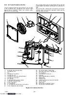
Page 19: ...ilation for commodities that require fresh air circulation 1 2 3 8 4 13 5 14 17 9 18 16 12 15 10 11 6 7 1 Access Panel Evap Fan 1 2 Access Panel Heaters Suction Modulating Valve Quench Expansion Valve Evaporator Expansion Valve 3 Fork Lift Pockets 4 Control Box 5 Compressor 6 Receiver or Water Cooled Condenser 7 Economizer 8 Unit Serial Number Model Number and Parts Identification Number PID Plate...

Page 20: ...s shown in the illustration or by removing the front access panels 19 17 15 16 1 2 3 4 6 7 9 10 14 20 22 11 8 12 5 ALTERNATE USDA LOCATION 26 21 23 24 25 18 13 1 Evaporator Fan Motor 1 2 Return Recorder Sensor 3 Return Temperature Sensor 4 Humidity Sensor 5 Mechanical Recorder Bulb 6 Evaporator Fan Motor 2 7 Defrost Temperature Sensor 8 Heater Termination Thermostat 9 Evaporator Coil 10 Evaporator...

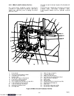
Page 21: ... 7 13 13 9 1 Compressor Guard 2 Supply Temperature Sensor 3 Supply Recorder Sensor 4 Ambient Sensor 5 Supply Air Thermometer Port location 6 Oil Drain 7 Compressor 8 Compressor Sight Glass 9 Compressor Power Plug 10 Discharge Service Valve Connection 11 High Pressure Switch 12 Access Valve Std tubing only 13 Access Valve 14 Economizer Service Valve Connection 15 Suction Service Valve Connection 16...

Page 22: ...2 23 24 25 26 10 13 1 Grille and Venturi Assembly 2 Condenser Fan 3 Key 4 Condenser Fan Motor 5 Condenser Coil 6 Condenser Motor Mounting Bracket 7 Condenser Coil Cover 8 Economizer 9 To Evaporator Expansion Valve 10 Unloader Solenoid Valve 11 From Condenser 12 To Condenser 13 To Compressor Economizer Connection 14 From Unloader Solenoid Valve 15 From Compressor Discharge 16 Discharge Pressure Tra...

Page 23: ...izer 2 To Evaporator Expansion Valve 3 Unloader Solenoid Valve 4 Rupture Disc 5 Discharge Pressure Transducer 6 From Air Cooled Condenser 7 To Air Cooled Condenser 8 To Compressor Economizer Connection 9 From Unloader Solenoid Valve 10 From Compressor Discharge 11 Oil Return Solenoid Valve 12 Oil Separator 13 Water Pressure Switch 14 Coupling Water In 15 Water Connection Caps 16 Self Draining Coup...

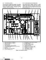
Page 24: ...ain power line Refer to the master system technicalmanual for further information 19 20 15 17 18 1 2 3 4 5 6 7 9 11 8 10 16 12 13 14 1 Compressor Phase A Contactor 2 Compressor Phase B Contactor 3 Heater Contactor 4 Display Module 5 Communications Interface Module 6 Controller DataCORDER Module Controller 7 Expansion Module 8 Key Pad 9 Remote Monitoring Receptacle 10 Controller Battery Pack 11 Int...

Page 25: ...8 4 _C 100 7 _F e High Pressure Switch Cutout 25 1 0 kg cm 350 10 psig e High Pressure Switch Cut In 18 0 7 kg cm 250 10 psig Unit Configuration Charge Requirements R 134a Water Cooled 4 Row Coil 5 Row Coil f Refrigerant Charge Water Cooled Condenser 5 56 kg 12 25 lbs 6 3 kg 13 75 lbs Receiver 5 22kg 11 5 lbs 5 9kg 13 lbs g Fusible Plug Melting point 99 _C 210 _F g Fusible Plug Torque 6 2 to 6 9 m...

Page 26: ...orator Coil Heaters Resistance cold 66 8 to 77 2 ohms 20 _C 68 _F Type Sheath 380 vac 50 hz 460 vac 60 hz Full Load Amps High Speed 1 6 2 0 Full Load Amps Low Speed 0 8 1 0 Nominal Horsepower High Speed 0 70 0 84 f Evaporator Fan Nominal Horsepower Low Speed 0 09 0 11 f Evaporator Fan Motor s Rotations Per Minute High Speed 2850 rpm 3450 rpm Rotations Per Minute Low Speed 1425 rpm 1750 rpm Voltage...

Page 27: ...Circuit Breaker CB 1 Manual Reset Trips at 29 amps 460 vac Excessive current draw Circuit Breaker CB 2 50 amp Manual Reset Trips at 62 5 amps 230 vac Circuit Breaker CB 2 70 amp Manual Reset Trips at 87 5 amps 230 vac Excessive current draw in the control circuit Fuse F3 10 amp rating Excessive current draw by the controller Fuse F1 F2 5 amp rating Excessive current draw by the expansion module Fu...

Page 28: ...tically started When operating a system fitted with a condenser fan switch the condenser fan will be off when the switch is placed in the O position The condenser fan will be on when the switch is placed in the I position 2 5 2 Economized Operation In the economized mode the frozen and pull down capacity of the unit is increased by subcooling the liquid refrigerant entering the evaporator expansio...

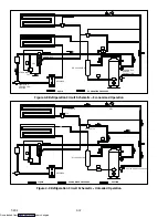
Page 29: ...LED CONDENSER QUENCH TXV BULB STS DPT CPDS RECEIVER FUSIBLE PLUG SIGHT GLASS MOISTURE INDICATOR LIQUID LINE SERVICE CONNECTION FILTER DRIER ECONOMIZER TXV ESV ECONOMIZER ECONOMIZER TXV BULB HPS OIL RETURN SERVICE VALVE DISCHARGE SERVICE CONNECTION SPT SUCTION SERVICE CONNECTION QUENCH TXV USV LOW SIDE ACCESS VALVE LOW SIDE ACCESS VALVE DISCHARGE LIQUID SUCTION ESV ECONOMIZER TXV LIQUID LINE SERVIC...

Page 30: ... CON NECTION OIL SEPARATOR RECEIVER Figure 2 8 Refrigeration Circuit Schematic Economized Operation LIQUID ECONOMIZER PRESSURE TXV TXV BULB SMV SUCTION SERVICE VALVE QUENCH TXV USV SUCTION OIL SEPARATOR RECEIVER Figure 2 9 Refrigeration Circuit Schematic Unloaded Operation Downloaded from ManualsNet com search engine ...

Page 31: ...taCORDERsoftware is provided in paragraph 3 6 The key pad and display module serve to provide user access and readouts for both of the controller functions temperature control and DataCORDER The functions are accessed by key pad selections and viewed on the display module The components are designed to permit ease of installation and removal TO DISPLAY CONTROL MODULE DISPLAY MODULE KEY PAD CONFIGU...

Page 32: ... scroll a selection down ward Pre trip repeat backward Return Supply Displays non controlling probe tem perature momentary display _C _F Displays alternate English Metric scale momentary display When set to _F pressure is displayed in psig and vacuum in hg P appears after the value to indicate psig and i ap pears for inches of mercury When set to _C pressure readings are in bars b appears after th...

Page 33: ...are and the Operational Software The controller software performs the following functions a Control supply or return air temperature to required limits provide modulated refrigeration operation economized operation unloaded operation electric heat control and defrost Defrost is performed to clear build up of frost and ice and ensure proper air flow across the coil b Provide default independent rea...

Page 34: ...n the supply air temperature enters the in range temperature tolerance as selected at function code Cd30 the in range light will energize 3 3 2 Defrost Interval Function code Cd27 may be operator set to initiate defrost at intervals of 3 6 9 12 or 24 hours It may also be set to OFF no defrost The factory default is 12 hours Refer to Table 3 5 3 3 3 Failure Action Function code Cd29 may be operator...

Page 35: ...ng air Removing water from the air reduces the relative humidity When the relative humidity sensed is 2 below the set point the controller de energizes the heat relay The controller will continue to cycle heating to maintain relative humidity below the selected set point If the mode is terminated by a condition other than the humidity sensor e g an out of range or compressor shutdown condition the...

Page 36: ...e turned off when the control temperature is less than or equal to the set point 2_C After an off cycle period of 60 minutes the unit will turn on high speed evaporator fans for three minutes and then check the control temperature If the control temperature is greater than or equal to the set point 0 2_C the unit will restart the refrigeration system and continue to cool until the previously menti...

Page 37: ...ts of Configuration Software Operational Software Data Storage Memory Real Time Clock with internal battery backup Six thermistor inputs Interrogation Connections Power supply battery pack The DataCORDER performs the following functions a Logs data at 15 30 60 or 120 minute intervals and stores two years of data based on one hour interval b Records and displays alarms on the display module c Recor...

Page 38: ...emperature control software uses the supply and return temperature sensors STS RTS b Generic Mode The generic recording mode allows user selection of the network data points to be recorded The user may select up to a total of eight data points for recording A list of the data points available for recording follows Changing the configuration to generic and selecting which data points to record may ...

Page 39: ...Origin Date Destination Discharge Date Comment DataLine Tool Probe Calibration Readings USDA1 0 0 USDA2 0 0 USDA3 0 0 Cargo 0 0 Temperature Units Centigrade ________________________________________________________________________________________ May 31 2001 Setpoint 1 66 Container Serial 04189552 9 Sensors Logged at 15 Minute Interval Sensor Format Resolution Figure 3 5 Standard Configuration Down...

Page 40: ...ower up for communication when an interrogation cable is plugged into an interrogation receptacle 3 External DC battery pack power A 12 volt battery pack may also be plugged into the back of the interrogation cable which is then plugged into an interrogation port No controller battery pack is required with this method 4 Real Time Clock demand If the DataCORDER is equipped with a charged battery pa...

Page 41: ...cles are sized to accept plugs with tricam coupling locking devices A label on the back panel of the unit shows which receptacle is used for each probe The standard DataCORDER report displays the supply and return air temperatures The cold treatment report displays USDA 1 2 3 and the supply and return air temperatures Cold treatment recording is backed up by a battery so recording can continue if ...

Page 42: ...e that a successful connection is established with the Controller If the connection is established with the DataCorder the current contents of the ISO Trip Header from the DataCorder will be displayed in each field If the connection is not established with the DataCorder all fields on the screen will be displayed as X s If at any time during the display of the ISO Trip Header screen the connection...

Page 43: ...requency dis played will be halved if either fuse F1 or F2 is bad alarm code AL21 Cd09 Ambient Tempera ture The ambient sensor reading is displayed Cd10 Compressor Suction Temperature Compressor suction temperature sensor reading is displayed Cd11 Compressor Dis charge Temperature Compressor discharge temperature sensor reading is displayed Cd12 Compressor Suction Pressure Compressor suction press...

Page 44: ...CnF23 If the software is configured to SAv save for this option then the value of the defrost interval timer will be saved at power down and restored at power up This option prevents short power interruptions from resetting an almost expired defrost interval and possibly delaying a needed defrost cycle NOTE The defrost interval timer counts only during compressor run time Cd28 Temperature Units _C...

Page 45: ...set to bulb If these conditions are not met alt will be displayed indicating that the evaporator fans will alternate their speed and the display cannot be changed If a dehumidification set point has been selected along with bulb mode then alt may be selected for alternating speed Lo for low speed evaporator fan only or Hi for high speed evaporator fan only If a setting other than alt has been sele...

Page 46: ...inutes within the last hour The alarm is display only and will trigger off when the compressor operates for one hour without overpressure AL19 Discharge Tempera ture High Alarm 19 is triggered if discharge temperature exceeds 135_C 275_F for 10 minutes within the last hour The alarm is display only and will trigger off when the compressor operates for one hour without over temperature AL20 Control...

Page 47: ...minute adjustment period the sensor will generate an alarm event The alarm is trig gered off when the unit power cycles and the sensor is within valid range AL51 Alarm List Failure During start up diagnostics the EEPROM is examined to determine validity of its contents This is done by testing the set point and the alarm list If the contents are invalid Alarm 51 is activated During control processi...

Page 48: ...y detection of improper amperage resulting from heater activation or deactivation Each phase of the power source is checked for proper amperage This alarm is a display alarm with no resulting failure action and will be reset by a proper amp draw of the heater AL62 Compressor Circuit Failure Alarm 62 is triggered by improper current draw increase or decrease resulting from compressor turn on or off...

Page 49: ...ram ERR Microprocessor Failure EER 2 Watchdog time out The Controller program has entered a mode where by the Controller program has stopped executing EER 3 On board timer failure The on board timers are no longer operational Timed items such as defrost etc may not work EER 4 Internal counter failure Internal multi purpose counters have failed These counters are used for timers and other items EER...

Page 50: ...ration variable P3 0 Low Speed Evapo rator Fan Motors On Setup The high speed evaporator fans will be turned on for 10 seconds then off for two seconds then the low speed evaporator fans are turned on A current draw test is done after 60 seconds Pass Fail Criteria Passes if change in current draw is within the range speci fied Fails if AL11 or AL12 activates during test for units operating with si...

Page 51: ...Monitor suc tion pressure Step 3 open suction modulation valve to a known position Step 4 close suction modulation valve to a know position Step 5 open economizer valve Step 6 close unloader valve Step 7 open unloader valve Step 8 close economizer valve Step 9 de energize all outputs P6 0 Discharge Thermistor Test If alarm 64 is activated any time during the first 45 second period of Step 1 the te...

Page 52: ...0 C set point Pass Fail Criteria The test passes if the container temperature reaches set point before the 180 minute timer expires P8 2 Perishable Mode Maintain Tempera ture Test Requirements Test P8 1 must pass for this test to execute This test is skipped if the dataCORDER is not configured or available Setup The left display will read P8 2 and the right display will show the supply air tempera...

Page 53: ...0 3_C 0 17_F before the 180 minute timer expires the test fails and will auto repeat by starting P10 0 over P10 2 Frozen Mode Maintain Temperature Test Requirements Test P10 1 must pass for this test to execute This test is skipped if the dataCORDER is not configured or available Setup During this test the left display will read P10 2 and the right display will show the supply air temperature A tw...

Page 54: ...ER serial number consists of eight characters Function code dC26 contains the first four characters Function code dC27 contains the last four characters This serial number is the same as the Controller serial num ber dC28 Minimum Days Left An approximation of the number of logging days remaining until the Data CORDER starts to overwrite the existing data dC29 Days Stored Number of days of data tha...

Page 55: ...harge Pressure Sensor Test Pass Fail Skip 6 3 Suction Pressure Sensor Test Pass Fail Skip 6 4 Compressor Current Draw Test Pass Fail Skip 6 5 Suction Modulation valve Test Pass Fail Skip 6 6 Economizer Valve Test Pass Fail Skip 6 7 Unloader Valve Test Pass Fail Skip 7 0 High Pressure Switch Closed Pass Fail Skip Result AMBS DPT or CPT if equipped Input values that component opens 7 1 High Pressure...

Page 56: ...rk Data Point 1 8 Out of Range The network data point is outside of its specified range The DataCORD ER is configured by default to record the supply and return recorder sen sors The DataCORDER may be configured to record up to 8 additional network data points An alarm number AL78 to AL85 is assigned to each configured point When an alarm occurs the DataCORDER must be inter rogated to identify the...

Page 57: ...Downloaded from ManualsNet com search engine ...

Page 58: ... 230 vac Power An autotransformer Figure 4 1 is required to allow operation on nominal 230 volt power It is fitted with a 230 vac cable and a receptacle to accept the standard 460 vac power plug The 230 volt cable is black in color while the 460 volt cable is yellow The transformer may also be equipped with a circuit breaker CB 2 The transformer is a step up transformer that will provide 380 460 v...

Page 59: ...tic above free blow NOTE The main air slide is in the fully closed position during reduced air flow operation d Air Sampling for Carbon Dioxide CO2 Level Loosen hex nuts and move the cover until the arrow on the cover is aligned with the atmosphere sampling port label Tighten the hex nuts and attach a 3 8 hose to the sampling port If the internal atmosphere content has reached an unacceptable leve...

Page 60: ...7 through Cd39 in accordance with desired operating parameters Refer to paragraph 3 2 2 4 7 3 Start Temperature Recorder Partlow Recorders a Open recorder door and wind mechanical clock or check battery of electronic recorder Be sure key isre turned to storage clip of mechanical recorder b Lift stylus pen by pulling the marking tip outward un til the stylus arm snaps into it s retracted position c...

Page 61: ...ervention When an automatic test fails it will be repeated once A repeated test failure will cause FAIL to be shown on the right display with the corresponding test num ber to the left The user may then press the DOWN ARROW to repeat the test the UP ARROW to skip to the next test or the PRE TRIP key to terminate test ing The unit will wait indefinitely until the user manu ally enters a command CAU...

Page 62: ...r up 2 At the end of every defrost 3 After every diagnostic check that does not fall out side of the limits as outlined above d Probe Check A defrost cycle probe check is accomplished by energizing just the evaporator motors for eight minutes at the end of the normal defrost At the end of the eight minute period the probes will be compared to a set of predetermined limits The defrost indicator wil...

Page 63: ...r PB is wired to run the compressor on L2 L1 and L3 thus providing reverse rotation 4 10 2 Sequence Of Operation Perishable Mode Cooling NOTE In the Conventional Perishable Mode of opera tion the evaporator motors run in high speed In the Economy Perishable Mode the fan speed is varied a With supply air temperature above set point and de creasing the unit will be cooling with the condenser fan mot...

Page 64: ...orator coil support will open the heating circuit if overheating occurs 4 10 4 Sequence Of operation Frozen Mode Cooling a With supply air temperature above set point and de creasing the unit will transition to economized cool ing with the condenser fan motor CF compressor motor CH economizer solenoid valve ESV low speed evaporator fan motors ES energized and the COOL light illuminated See Figure ...

Page 65: ...compressor condenser fan and evaporator fans The COOL light is also de energized The controller then closes TH to supply power to the heaters The defrost light is illuminated When the defrost temperature sensor reading rises to the defrost termination thermostat setting the de icing operation is terminated If defrost does not terminate correctly and temperature reaches the set point of the heat te...

Page 66: ...tor 4 The evaporator fan contact will close to energize the high speed evaporator contactor and provide power to the evaporator fan motor 5 The EBS electronic module will open the SMV to 100 To return the unit to normal operation place the EBS switch in the NORMAL OPERATION position When emergency operation is no longer required re install the wire tie at the switch mounting 4 11 2 Emergency Defro...

Page 67: ...nt sensor Replace Low line voltage Check Compressor hums but does not Single phasing Check Compressor hums but does not start Shorted or grounded motor windings 6 5 Compressor seized 6 5 5 2 UNIT OPERATES LONG OR CONTINUOUSLY IN COOLING Container Hot load Normal Container Defective box insulation or air leak Repair Shortage of refrigerant 6 4 Evaporator coil covered with ice 5 6 Evaporator coil pl...

Page 68: ...wer Evaporator fan internal motor protector open 6 15 No control power Heat relay defective Check Heater termination thermostat open 6 13 Heater s defective 6 13 Heater contactor or coil defective Replace Evaporator fan motor s defective or rotating backwards 6 13 6 15 Unit will not heat or has insuffi Evaporator fan motor contactor defective Replace Unit will not heat or has insuffi cient heat Co...

Page 69: ...partially closed Open Filter drier partially plugged 6 11 Low refrigerant charge 6 4 Low suction pressure Expansion valve defective 6 12 Low suction pressure No evaporator air flow or restricted air flow 6 13 Excessive frost on evaporator coil 5 6 Evaporator fan s rotating backwards 6 15 3 Suction modulation valve malfunction 6 18 Suction and discharge pres sures tend to equalize when unit Compres...

Page 70: ...rrect 6 12 1 superheat Power assembly failure Loss of element bulb charge 6 12 Broken capillary 6 12 Foreign material in valve Hi h i i h l Superheat setting too low 6 12 High suction pressure with low superheat External equalizer line plugged Ice holding valve open Open superheat Foreign material in valve 6 12 Liquid slugging in compressor Pin and seat of expansion valve eroded or held open by fo...

Page 71: ...ct wiring of current sensor Check 5 15 ABNORMAL TEMPERATURES Discharge temperature sensor drifting high Replace High discharge temperature Failed economizer TXV or solenoid valve Replace High discharge temperature Plugged economizer TXV or solenoid valve Replace Loose or insufficiently clamped sensor Replace Low suction temperature Discharge temperature sensor drifting low Replace Low suction temp...

Page 72: ...an be checked When both valves are open all the way out high pressure vapor will flow into the low side When the suction pressure valve is open and the discharge pressure valve shut the system can be charged Oil can also be added to the system A R 134a manifold gauge hose set with self sealing hoses see Figure 6 2 is required for service of the models covered within this manual The manifold gauge ...

Page 73: ... gauge set to be drawn down to low side pressure This returns any liquid that may be in the high side hose to the system 3 Backseat the low side service valve Backseat both field service couplings and frontseat both manifold hand valves Remove the couplings from the access valves 4 Install both service valve stem caps and service port caps finger tight only 6 3 2 Pumping Down the Unit To service t...

Page 74: ...tems The presence of moisture in a refrigeration system can have many undesirable effects The most common are copper plating acid sludge formation freezing up of metering devices by free water and formation of acids resulting in metal corrosion Preparation a Evacuate and dehydrate only after pressure leak test b Essential tools to properly evacuate and dehydrate any system include a vacuum pump 8 ...

Page 75: ...rocedures of the preceding paragraph except leave compressor service valves frontseated until evacuation is completed b If refrigerant charge has been removed from the low side only evacuate the low side by connecting the evacuation set up at the compressor suction and economizer service valves and the liquid service valve except leave the service valves frontseated un til evacuation is completed ...

Page 76: ... be removed from system before performing service To connect the manifold gauge hose set for reading pressures do the following 1 Remove access valve cap See Figure 2 3 2 Connect the field service coupling to the access valve 3 Turn the field service coupling knob clockwise which will open the system to the gauge set 4 Repeat the procedure to connect the other side of the gauge set CAUTION To prev...

Page 77: ...ement and an electronic vacuum gauge The pump is available from Carrier Transicold P N 07 00176 11 Additional time may be saved during a complete system pump down by replaceing the filter drier with a section of copper tubing Procedure a Remove all refrigerant using a refrigerant recovery system Refer to section 6 4 2 b The recommended method to evacuate and dehy drate the system is to connect eva...

Page 78: ...ld be at the center of the glass If the refrigerant level is not correct go to section 6 4 7 6 4 7 Adding Refrigerant to System Partial Charge a Examine the unit refrigerant system for any evidence of leaks Repair as necessary b Maintain the conditions outlined in paragraph 6 4 5 c Connect charging line between suction line and cylin der of refrigerant R 134a Open VAPOR valve d Slowly add charge u...

Page 79: ... for safe keeping Plug the top of the replacement compressor sight glass with the plug kit item 5 to prevent spilling oil Resilient Mount Kit Item 6 Mylar Washer Kit Item 3 Mylar Protector Retain Base Plate Retain Mylar Protector Retain SST Washer Kit Item 10 SST Washer Kit Item 10 Figure 6 8 Compressor Lower Mounting k Remove the lower mounting bolts and hardware see Figure 6 8 Using plugs from r...

Page 80: ...into the compressor through the oil return service valve Connect the suction connection of the gauge man ifold to the compressor oil return valve port and immerse the common connection of the gauge man ifold in an open container of refrigeration oil Extreme care must be taken to ensure the manifold common connection remains immersed in oil at all times Otherwise air and moisture will be drawn into...

Page 81: ...eter will indicate open circuit g Slowly open bleed off valve to decrease the pres sure The switch should close at 18 kg cm 250 psig 6 8 CONDENSER COIL The condenser consists of a series of parallel copper tubes expanded into copper fins The condenser coil must be cleaned with fresh water or steam so the airflow is not restricted To replace the coil do the following WARNING Do not open the condens...

Page 82: ...32 available as a liquid in cases each containing 3 785 liters 4 U S gallon bottles and also in carboys of 52 6 kg 116 lbs net 3 Fresh clean water 4 Acid proof pump and containers or bottles with rub ber hose NOTE When Oakite compound No 32 is being used for the first time the local Oakite Technical Ser vice representative should be called in for their suggestions in planning the procedure They wi...

Page 83: ...ompleted is to titrate the solution periodically using titrating equip ment provided free by the Oakite Technical Service representative As scale is being dissolved titrate readings will indicate that the Oakite No 32 solution is losing strength When the reading remains constant for a reasonable time this is an indication that scale has been dissolved Fill condenser with clean ing solution Do not ...

Page 84: ...he load 2 Prevention of liquid refrigerant entering the com pressor Unless the valve is defective it seldom requires maintenance other than periodic inspection to ensure that the thermal bulb is tightly secured to the suction line and wrapped with insulating compound See Figure 6 12 1 2 3 4 1 Suction Line 2 TXV Bulb Clamp 3 Nut and Bolt 4 TXV Bulb Figure 6 12 Thermostatic Expansion Valve Bulb 6 12...

Page 85: ... unit per paragraph 6 3 2 Evacuate if unit is not equipped with service valves Refer to paragraph 6 4 4 2 Remove cushion clamps located on the inlet andout let lines 3 Unbraze the equalizer connection if applicable the outlet connection and then the inlet connection 4 Remove insulation Presstite from expansion valve bulb 5 Unstrap the bulb located below the center of the suction line 4 o clock pos...

Page 86: ...support and remove 6 14 ECONOMIZER UNLOADER AND OIl RETURN SOLENOID VALVE a Replacing the Coil NOTE The coil may be replaced without removing the refrigerant 1 Be sure electrical power is removed from the unit Disconnect leads Remove top screw and washer Lift off coil See Figure 6 16 or Figure 6 17 2 Verify coil type voltage and frequency of old andnew coil This information appears on the coil hou...

Page 87: ...rom the unit and place on a sturdy work surface 6 15 2 Disassemble The Evaporator Fan Assembly a Attach a spanner wrench to the two 1 4 20 holes located in the fan hub Loosen the 5 8 18 shaft nut by holding the spanner wrench stationary and turning the 5 8 18 nut counter clockwise see Figure 6 18 b Remove the spanner wrench Use a universal wheel puller and remove the fan from the shaft Remove the ...

Page 88: ...ard zero resistance and then gradually swing back toward a very high resistance reading If the capacitor has failed open the ohmmeter needle will not move when the meter probes touch the terminals If the capacitor is shorted the needle will swing to zero resistance position and stay there 2 Capacitor analyzer The function of the analyzer is to read the microfarad value of a capacitor and to detect...

Page 89: ...he valve will make a ratcheting noise that may be heard or felt as it is attempting to close If this can be heard or felt it indicates that the control ler and drive module are attempting to close the valve and may serve as a quick indication that the drive is in working order e Operation of the valve may be checked using the con troller valve override program function code Cd41 Refer to paragraph...

Page 90: ... wrist strap CAUTION Unplug all module connectors before per forming arc welding on any part of the con tainer The guidelines and cautions provided herein should be followed when handling the modules These precautions and procedures should be implemented when replacing a module when doing any arc welding on the unit or when service to the refrigeration unit requires handling and removal of a modul...

Page 91: ... program ming software port and return the unit to normal op eration by placing the start stop switch in the ON position b Procedure for loading Configuration Software 1 Turn unit OFF using start stop switch ST 2 Insert the programming card for Configuration Soft ware into the programming software port See Figure 6 20 3 Turn unit ON using start stop switch ST 4 The Display module will show nt40 on...

Page 92: ...Using the plug connector marked EC that is con nected to the back of the controller locate the sensor wires RRS RTS SRS STS AMBS DTS CPDS OR CPSS as required Follow those wires to the con nector and using the pins of the plug measure the resistance Values are provided in Table 6 2 Due to the variations and inaccuracies in ohmmeters thermometers or other test equipment a reading within 2 of the cha...

Page 93: ...urn Sensor Mounting Clamp Enlarged Positioning Plastic Section Figure 6 24 Return Sensor Positioning c Sensor DTS The DTS sensor must have insulating material placed completely over the sensor to insure the coil metal temperature is sensed 6 22 ELECTRONIC PARTLOW TEMPERATURE RECORDER The microprocessor based temperature recorder is designed to interface with the DataCORDER to log temperature with ...

Page 94: ...emove the chart retaining nut item 10 remove the used chart and record today s date on the old chart c Press the Change Chart button item 2 NOTE Failure to press the change chart button when changing a chart with the power OFF may result in the chart advancing when power is applied d Install a new chart make sure the chart center hole is placed over the center hub and the chart edges are behind th...

Page 95: ...lly down scale then move upscale to the chart ring at 0 C 32 F and stop b If the tip of the pen item 4 is on the 0 C 32 F chart ring the recorder is in calibration proceed to step c If the tip of the pen is NOT on the 0 C 32 F chart ring the operator must loosen the twoscrews onthe bottom of the stylus arm to adjust the pen tip manually to the 0 C 32 F chart ring Tighten the screws when adjustment...

Page 96: ...lb with ice cubes or chipped ice filling voids between ice with water and agitating until mixture reaches 0 C 32 F as shown by a laboratory thermometer When the ice bath temperature reaches 0 C 32 F as shown by the laboratory thermometer reading compare the temperature indicated by stylus with temperature shown by the thermometer Allow sufficient time to ensure bulb has cooled to the ice bath temp...

Page 97: ...efer to sections 6 23 a through 6 23 d 9 Install inlet air grille and upper panel Start unit and check recorder calibration 6 24 SAGINOMIYA TEMPERATURE RECORDER NOTE Do not overtighten chart nut after replacing chart 6 24 1Battery Check a Open door and remove chart nut and platen b Push voltage indicator test switch item 3 Figure 6 27 Replace battery if voltage indicator points to the red or white...

Page 98: ...rature e Rotate the adjustment screw counterclockwise to set the stylus about 0 5 C 0 9 F higher than set temperature Rotate the chart by hand The indicated temperature should be 0 C 32 F 6 24 3Replacing Sensor Probe a Remove box from unit b Remove nut and bushing item 18 Figure 6 27 c Install replacement probe and bushing Seal with silicone before securing to case d Install box into unit 16 17 18...

Page 99: ...ges of the patch 6 26 3 Chips And Holes Chips and holes in the control box are repaired using a piece of aluminum or stainless steel to cover the damaged area The material can be cut to suit and riveted in place An adhesive sealant must be used to make the repair watertight The adhesive sealant Sikaflex 221 is included in Crack Repair Kit Carrier Transicold part number 76 00724 00SV see Table 6 4 ...

Page 100: ...Kit Includes 76 50084 00 1 2 Insert 17 53 x 9 91 mm 690 x 390 in 1 4 20 Threads 34 06231 01 10 3 Insert 15 88 x 6 35 mm 625 x 250 in 10 24 Threads 34 06231 03 10 4 Insert 25 15 x 7 54 mm 990 x 297 in 10 24 Threads 34 06231 04 10 5 Insert 10 16 x 9 53 mm 400 x 375 in 10 24 Threads 34 06231 05 10 6 Insert 12 7 x 9 91 mm 5 x 390 in 1 4 20 Threads 34 06231 06 10 7 Insert 9 53 x 6 76 mm 375 x 266 in 10...

Page 101: ...6 30 T 292 03 03 03 03 04 04 03 01 07 07 05 05 06 INSERT PART NUMBERS 34 06231 WHERE THE IS AS INDICATED Figure 6 29 Insert Location Downloaded from ManualsNet com search engine ...

Page 102: ...ircuit breaker panel with circuit breaker from the control box d Locate wires CB21 CIA3 CB22 CIA5 and CB23 CIA7 that have been tied back in the wire harness Remove the protective heat shrink from the ends of the wires e Attach the three wires as addressed to the LOAD side of the circuit breaker f Refit the circuit breaker panel g Fit the new RMU into the unit h Remove plugs CIA CIB and CID from th...

Page 103: ...37 2 1 40 1 37 24 4 21 4 147 6 1 50 1 48 26 3 22 9 157 9 1 61 1 58 Temperature Pressure _ _ _ _F _ _ _ _C psig kPa kg cm bar 28 2 24 5 168 9 1 72 1 69 30 1 26 1 180 0 1 84 1 80 32 0 27 8 191 7 1 95 1 92 34 1 29 6 204 1 2 08 2 04 36 2 31 3 215 8 2 20 2 16 38 3 33 2 228 9 2 33 2 29 40 4 35 1 242 0 2 47 2 42 45 7 40 1 276 5 2 82 2 76 50 10 45 5 313 7 3 20 3 14 55 13 51 2 353 0 3 60 3 53 60 16 57 4 39...

Page 104: ...Downloaded from ManualsNet com search engine ...

Page 105: ...P 10 ED EMERGENCY DEFROST EM EVAPORATOR FAN MOTOR E 13 G 13 T 8 T 11 ES EVAPORATOR FAN CONTACTOR LOW M 14 P 7 P 10 ESV ECONOMIZER SOLENOID VALVE J 17 F FUSE C 5 D 20 E 20 H 5 FT FUSE TransFRESH H 5 HPS HIGH PRESSURE SWITCH G 11 HR HEATER CONTACTOR M 15 N 3 HS HUMIDITY SENSOR F 21 HTT HEAT TERMINATION THERMOSTAT G 15 IC INTERROGATOR CONNECTOR FRONT REAR P 22 P 21 IP INTERNAL PROTECTOR E 13 G 13 H 1...

Page 106: ...7 2 T 292 Figure 7 2 SCHEMATIC DIAGRAM Downloaded from ManualsNet com search engine ...

Page 107: ...C R ELECTRONIC PARTLOW TEMPERATURE RECORDER Chart Recorder TO CI SEE Figure 7 2 NOTE STANDARD CONTROLLER JUMPERS MA3 TO MA7 AND MA9 TO MA11 SEE Figure 7 2 ARE REMOVED IN THIS APPLICATION C1 C5 C6 TransFRESH CONTROLLER TO DL TERMINAL C ST TR Figure 7 3 SCHEMATIC DIAGRAM Temperature Recorders Downloaded from ManualsNet com search engine ...

Page 108: ...RESSES FOR THE CHANGED DESTINATIONS ARE SHOWN IN BRACKETS XXX SEE Figure 7 6 ICF MAY BE IN CONTROL BOX SINGLE SENSOR CONFIGURATION COMBINATION SENSOR CFS1 Figure 7 4 WIRING DIAGRAM UNITS W SINGLE CAPACITOR EVAPORATOR FAN MOTOR Sheet 1 of 2 Downloaded from ManualsNet com search engine ...
Page 109: ...GE FROM THE STANDARD ADDRESSES FOR THE CHANGED DESTINATIONS ARE SHOWN IN BRACKETS XXX CFS KA6 CFA1 CFS2 ED11 ED12 ED6 ED9 ED2 ED 11 Figure 7 4 WIRING DIAGRAM UNITS W SINGLE CAPACITOR EVAPORATOR FAN MOTOR Sheet 2 of 2 Downloaded from ManualsNet com search engine ...

Page 110: ...GE FROM THE STANDARD ADDRESSES FOR THE CHANGED DESTINATIONS ARE SHOWN IN BRACKETS XXX CFS1 SEE Figure 7 6 ICF MAY BE IN CONTROL BOX Figure 7 5 WIRING DIAGRAM UNITS W DUAL CAPACITOR EVAPORATOR FAN MOTORS Sheet 1 of 2 Downloaded from ManualsNet com search engine ...
Page 111: ...TINATIONS CHANGE FROM THE STANDARD ADDRESSES FOR THE CHANGED DESTINATIONS ARE SHOWN IN BRACKETS XXX CFS KA6 CFA1 CFS2 FIGURE 7 5 WIRING DIAGRAM UNITS W DUAL CAPACITOR EVAPORATOR FAN MOTORS Sheet 2 of 2 Downloaded from ManualsNet com search engine ...
Page 112: ...RS MA3 TO MA7 AND MA9 TO MA11 SEE Figure 7 4 Sheet 1 ARE REMOVED IN THIS APPLICATION See Figure 7 4 Sheet 1 See Figure 7 4 Sheet 2 Figure 7 6 WIRING DIAGRAM Electronic Partlow Temperature Recorder Downloaded from ManualsNet com search engine ...
Page 113: ...R 3 7 3 10 4 3 DataCORDER Software 3 7 DataReader 3 10 DataView 3 11 Defrost Interval 3 4 Defrost Mode 4 7 Dehumidification 1 1 Display Module 3 2 E Emergency Bypass 4 9 Emergency Defrost 4 9 Evacuation 6 3 6 6 Evaporator 6 15 Evaporator Fan 1 2 6 16 Evaporator Section 2 2 Expansion Module 3 1 6 19 Expansion Valves 6 13 F Failure Action 3 4 Filter Drier 6 13 Fresh Air Makeup 2 1 4 1 Frozen Mode 4 ...

Page 114: ... Refrigeration System Data 2 7 Refrigeration Unit Front Section 2 1 Remote Monitoring 1 1 S Safety and Protective Devices 2 9 Sampling Type 3 10 Sensor Configuration 3 8 Sequence Of Operation 4 5 Service Valves iv 6 5 Solenoid Valves 6 15 Starting 4 3 Stopping 4 3 Suction Modulating Valve 6 18 T Temperature Control 3 4 3 6 Temperature Readout 1 1 Temperature Recorder 1 2 4 3 6 22 6 24 6 26 Tempera...

Reviews: