T-292
2-3
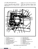
2.1.4 Compressor Section
The compressor section includes the compressor (with
high pressure switch) and the oil separator.
This section also contains the oil return solenoid,
compressor power plug, the discharge pressure
transducer and the suction pressure transducers.
The supply temperature sensor, supply recorder sensor
and ambient sensor are located at the left side of the
compressor.
12
14
1
2
3
4
5
6
8
10 11
19
20
21
22
23
24
18
17
12
15
25
16
Discharge
Connection
(Hidden)
Economizer
Connection
Suction
Connection
Oil Return
Connection
7
13
13
9
1. Compressor Guard
2. Supply Temperature Sensor
3. Supply Recorder Sensor
4. Ambient Sensor
5. Supply Air Thermometer Port (location)
6. Oil Drain
7. Compressor
8. Compressor Sight Glass
9. Compressor Power Plug
10. Discharge Service Valve/Connection
11. High Pressure Switch
12. Access Valve (Std. tubing only)
13. Access Valve
14. Economizer Service Valve/Connection
15. Suction Service Valve/Connection
16. Discharge Temperature Sensor
17. Oil Return Service Valve (Std. tubing only)
18. Discharge Pressure Transducer
19. Oil Return Solenoid Valve
20. Oil Separator
21. From Economizer
22. To Condenser
23. From Suction Modulating Valve
24. Suction Strainer
25. Suction Pressure Transducer
Figure 2-3 Compressor Section
Downloaded from
Summary of Contents for 69NT40-531 Series
Page 2: ...Downloaded from ManualsNet com search engine ...
Page 4: ...Downloaded from ManualsNet com search engine ...
Page 8: ...Downloaded from ManualsNet com search engine ...
Page 16: ...Downloaded from ManualsNet com search engine ...
Page 57: ...Downloaded from ManualsNet com search engine ...
Page 104: ...Downloaded from ManualsNet com search engine ...
Page 106: ...7 2 T 292 Figure 7 2 SCHEMATIC DIAGRAM Downloaded from ManualsNet com search engine ...

