3-1
T-292
SECTION 3
MICROPROCESSOR
3.1 TEMPERATURE CONTROL MICROPRO-
CESSOR SYSTEM
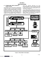
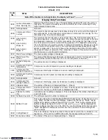
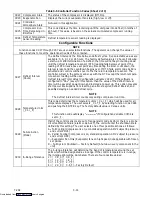
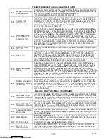
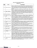
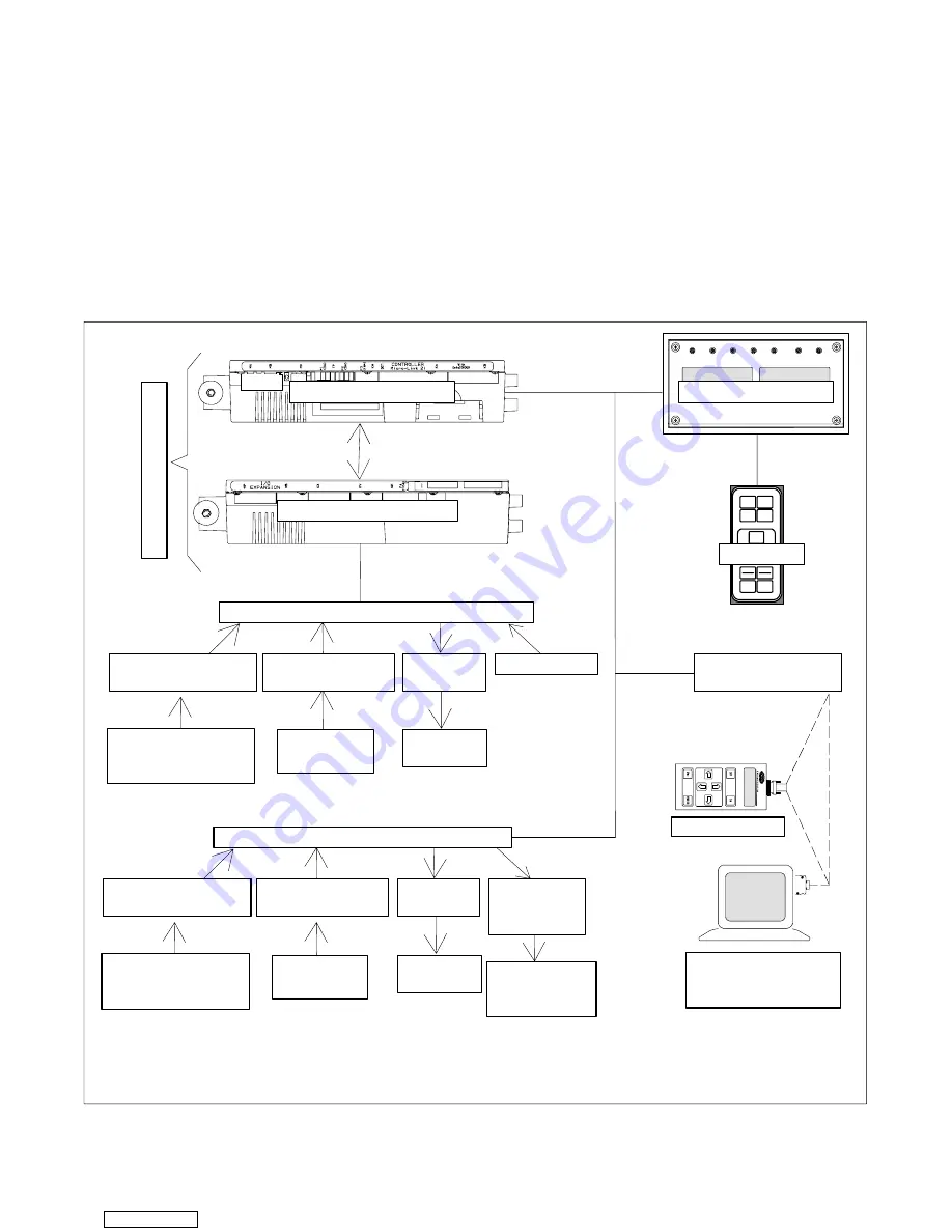
The temperature control Micro-Link 2i microprocessor
system (see Figure 3- 1) consists of a key pad, display
module, the control module & expansion module set
(controller) and interconnecting wiring. The controller
houses the temperature control software and the
DataCORDER Software. The temperature control
software functions to operate the unit components as
required to provide the desired cargo temperature and
humidity. The DataCORDER software functions to
record
unit
operating parameters
and cargo
temperature parameters for future retrieval. Coverage
of the temperature control software begins with
paragraph 3.2. Coverage of the DataCORDER software
is provided in paragraph 3.6.
The key pad and display module serve to provide user
access and readouts for both of the controller functions,
temperature control and DataCORDER. The functions
are accessed by key pad selections and viewed on the
display module. The components are designed to
permit ease of installation and removal.
TO
DISPLAY
CONTROL MODULE
DISPLAY MODULE
KEY PAD
CONFIGURATION
SOFTWARE
CONFIGURATION
VARIABLE
(CnF##)
TEMPERATURE CONTROL SOFTWARE
ALARMS
(AL<70)
PRE--TRIP
INTERROGATION
CONNECTOR
DATAREADER
Computer Device
With DataLine
Software
DataCORDER SOFTWARE
OPERATIONAL
SOFTWARE
FUNCTION
CODE (Cd)
TO
DISPLAY
CONFIGURATION
SOFTWARE
CONFIGURATION
VARIABLE
(dCF## read only)
ALARMS
(AL>69)
DATA
STORAGE
MEMORY
OPERATIONAL
SOFTWARE
FUNCTION
CODE (dC)
TO
DISPLAY
(Scrollback)
EXPANSION MODULE
C
O
N
T
R
O
L
L
E
R
Figure 3- 1 Temperature Control System
Downloaded from
Summary of Contents for 69NT40-531 Series
Page 2: ...Downloaded from ManualsNet com search engine ...
Page 4: ...Downloaded from ManualsNet com search engine ...
Page 8: ...Downloaded from ManualsNet com search engine ...
Page 16: ...Downloaded from ManualsNet com search engine ...
Page 57: ...Downloaded from ManualsNet com search engine ...
Page 104: ...Downloaded from ManualsNet com search engine ...
Page 106: ...7 2 T 292 Figure 7 2 SCHEMATIC DIAGRAM Downloaded from ManualsNet com search engine ...

