3-12
T-292
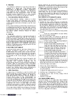
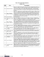
To display alarm codes:
a. While in the Default Display mode, press the ALT.
MODE & ALARM LIST keys. This accesses the Data-
CORDER Alarm List Display Mode, which displays
any alarms stored in the Alarm Queue.
b. To scroll to the end of the alarm list press the UP AR-
ROW. Depressing the DOWN ARROW key will scroll
the list backward.
c. The left display will show “AL#” where # is the alarms
number in the queue. The right display will show
“AA##,” if the alarm is active, where ## is the alarm
number. “IA##,” will show if the alarm is inactive
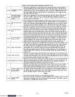
d. “END” is displayed to indicate the end of the alarm list
if any alarms are active. “CLEAr” is displayed if all the
alarms in the list are inactive.
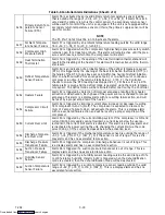
e. If no alarms are active, the Alarm Queue may be
cleared. The exception to this rule is the DataCORD-
ER Alarm Queue Full alarm (AL91) , which does not
have to be inactive in order to clear the alarm list. To
Clear the Alarm List:
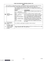
1. Press the ALT. MODE & ALARM LIST keys.
2. Press the UP/DOWN ARROW key until “CLEAr” is
displayed.
3. Press the ENTER key. The alarm list will clear and
“
-- -- -- -- --
” will be displayed.
4. Press the ALARM LIST key. “AL” will show on the left
display and “
-- -- -- -- --
” on the right display when
there are no alarms in the list.
5. Upon clearing of the Alarm Queue, the Alarm light will
be turned off.
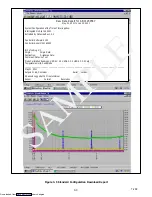
3.6.14 ISO Trip Header
DataLine provides the user with an interface to
view/modify current settings of the ISO trip header
through the ISO Trip Header screen.
The ISO Trip Header screen is displayed when the user
clicks on the “ISO Trip Header” button in the “Trip
Functions” Group Box on the System Tools screen.
F9 function -- Provides the user with a shortcut for
manually triggering the refresh operation.Before
sending modified parameter values, the user must
ensure that a successful connection is established with
the Controller.
If the connection is established with the DataCorder, the
current contents of the ISO Trip Header from the
DataCorder will be displayed in each field. If the
connection is not established with the DataCorder, all
fields on the screen will be displayed as “X’s”.If at any
time during the display of the ISO Trip Header screen
the connection is not established or is lost, the user is
alerted to the status of the connection.
After modifying the values and ensuring a successful
connection has been made with the DataCorder, click
on the “Send” button to send the modified parameter
values.
The maximum allowed length of the ISO Trip Header is
128 characters.If the user tries to refresh the screen or
close the utility without sending the changes made on
the screen to the DataCorder, the user is alerted with a
message.
Table 3-4 Controller Configuration Variables
NOTES
1. Configuration numbers not listed are not used in this application. These items may appear when loading
configuration software to the controller but changes will not be recognized by the controller programming.
CONFIGURATION
NUMBER
TITLE
DEFAULT
OPTION
CnF02
Evaporator Fan Speed
dS (Dual)
SS (Single)
CnF04
Dehumidification Mode
On
OFF
CnF11
Defrost “Off” Selection
noOFF
OFF
CnF16
DataCORDER Present
On (Yes)
OFF (No)
CnF22
Economy Mode Option
OFF
Std, Full
CnF23
Defrost Interval Timer Save Option
noSAv
SAv
CnF24
Long Pre Trip Test Sequence Enabled
On
Off
CnF25
Pre-Trip Test Points/Results Recording Option
rSLtS
dAtA
CnF26
Heat Lockout Change Option
Set to --10
_
C
Set to --5
_
C
CnF28
Bulb Mode Option
NOr
bULb
CnF31
Probe Check Option
Std
SPEC
CnF33
Snap Freeze Option
OFF
SnAP
CnF34
Degree Celsius/Fahrenheit Lockout Option
bOth
_
C,
_
F
CnF37
Electronic Temperature Recorder
rEtUR (Return)
suPPl, BOth
CnF47
Fresh Air Vent Position Sensor
OFF
UPP, LOW
Downloaded from
Summary of Contents for 69NT40-531 Series
Page 2: ...Downloaded from ManualsNet com search engine ...
Page 4: ...Downloaded from ManualsNet com search engine ...
Page 8: ...Downloaded from ManualsNet com search engine ...
Page 16: ...Downloaded from ManualsNet com search engine ...
Page 57: ...Downloaded from ManualsNet com search engine ...
Page 104: ...Downloaded from ManualsNet com search engine ...
Page 106: ...7 2 T 292 Figure 7 2 SCHEMATIC DIAGRAM Downloaded from ManualsNet com search engine ...


