3-16
T-292
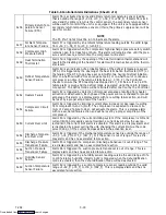
Table 3-6 Controller Alarm Indications
(Sheet 1 of 4)
Code
No.
TITLE
DESCRIPTION
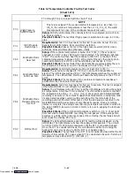
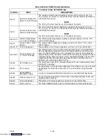
AL13 Expansion Module
Alarm 13 is triggered if the control module has lost communication with the ex-
pansion module for more than five minutes or communication fails within the first
15 seconds on power up. This alarm triggers failure action C (evaporator fan
only) or D (all machinery off) of Function Code Cd29 if the unit has a perishable
set point. Failure action D (all machinery off) is triggered if the unit has a frozen
set point
AL14 Phase Sequence
Failure -- Electronic
Alarm 14 is triggered if the electronic phase detection system is unable to deter-
mine the correct phase relationship. DIRCHECK will be displayed while the rela-
tionship is determined. If the system is unable to determine the proper relation-
ship alarm 14 will remain active. Additional information on phase detection may
be displayed at Function Code Cd41. If the right most digit of Code Cd41 is 3 or
4, this indicates incorrect motor or sensor wiring. If the right most digit is 5, this
indicates a failed current sensor assembly.
AL15 Loss of Cooling
Future Expansion
AL16 Compressor Current
High
Alarm 16 is triggered if compressor current draw is 15% over calculated maxi-
mum for 10 minutes out of the last hour. The alarm is display only and will trigger
off when the compressor operates for one hour without over current.
AL17 Phase Sequence
Failure -- Pressure
Alarm 17 is triggered if a compressor start in both directions fails to generate suf-
ficient pressure differential. The controller will attempt restart every twenty min-
utes and deactivate the alarm if successful. This alarm triggers failure action C
(evaporator fan only) or D (all machinery off) of Function Code Cd29 if the unit
has a perishable set point. Failure action D (all machinery off) is triggered if the
unit has a frozen set point
AL18 Discharge Pressure
High
Alarm 18 is triggered if discharge pressure is 10% over calculated maximum for
10 minutes within the last hour. The alarm is display only and will trigger off when
the compressor operates for one hour without overpressure.
AL19 Discharge Tempera-
ture High
Alarm 19 is triggered if discharge temperature exceeds 135
_
C (275
_
F) for 10
minutes within the last hour. The alarm is display only and will trigger off when
the compressor operates for one hour without over temperature.
AL20 Control Circuit Fuse
Open (24 vac)
Alarm 20 is triggered by control power fuse (F3) opening and will cause the soft-
ware shutdown of all control units. This alarm will remain active until the fuse is
replaced.
AL21 Micro Circuit Fuse
Open (18 vac)
Alarm 21 is triggered by one of the fuses (F1/F2) being opened on 18 volts AC
power supply to the Controller. The suction modulation valve (SMV) will be
opened and current limiting is halted. Temperature control will be maintained by
cycling the compressor.
AL22 Evaporator Fan Mo-
tor Safety
Alarm 22 responds to the evaporator motor internal protectors. The alarm is trig-
gered by opening of either internal protector. It will disable all control units until
the motor protector resets and the unit is power cycled.
AL23 Loss of Phase B
Alarm 23 is triggered if low current draw is detected on phase B and IPCP, HPS
or IPEM is not tripped. If the compressor should be running, the controller will
initiate a start up every five minutes and trigger off, if current reappears. If the
evaporator fan motors only should be running, the alarm will trigger off is current
reappears. This alarm triggers failure action C (evaporator fan only) or D (all ma-
chinery off) of Function Code Cd29 if the unit has a perishable set point. Failure
action D (all machinery off) is triggered if the unit has a frozen set point
AL24 Compressor Motor
Safety
Alarm 24 is triggered when compressor is not drawing any current. It also triggers
failure action ”C” or ”D” set by function Code 29 for perishable setpoint, or ”D” for
frozen setpoint. If the compressor should be running, the controller will initiate a
start up every five minutes and trigger off, if current reappears. This alarm will
remain active until compressor draws current.
Downloaded from
Summary of Contents for 69NT40-531 Series
Page 2: ...Downloaded from ManualsNet com search engine ...
Page 4: ...Downloaded from ManualsNet com search engine ...
Page 8: ...Downloaded from ManualsNet com search engine ...
Page 16: ...Downloaded from ManualsNet com search engine ...
Page 57: ...Downloaded from ManualsNet com search engine ...
Page 104: ...Downloaded from ManualsNet com search engine ...
Page 106: ...7 2 T 292 Figure 7 2 SCHEMATIC DIAGRAM Downloaded from ManualsNet com search engine ...

