3-18
T-292
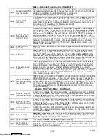
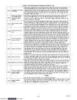
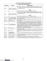
Table 3-6 Controller Alarm Indications (Sheet 3 of 4)
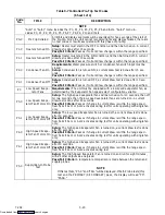
AL56
Primary Return Tem-
perature Sensor
Failure (RTS)
Alarm 56 is activated by an invalid primary return temperature sensor reading
that is outside the range of --50 to +70
_
C (--58
_
F to +158
_
F). If Alarm 56 is acti-
vated and the primary return is the control sensor, the secondary return sensor
will be used for control if the unit is so equipped. If the unit is not equipped with a
secondary return temperature sensor or it fails, the primary supply sensor will be
used for control.
NOTE
The P5 Pre-Trip test must be run to inactivate the alarm.
AL57 Ambient Tempera-
ture Sensor Failure
Alarm 57 is triggered by an ambient temperature reading outside the valid range
from --50
_
C (--58
_
F) to +70
_
C (+158
_
F).
AL58 Compressor High
Pressure Safety
Alarm 58 is triggered when the compressor high discharge pressure safety switch
remains open for at least one minute. This alarm will remain active until the pres-
sure switch resets, at which time the compressor will restart.
AL59 Heat Termination
Thermostat
Alarm 59 is triggered by the opening of the heat termination thermostat and will
result in the disabling of the heater. This alarm will remain active until the thermo-
stat resets.
AL60 Defrost Temperature
Sensor Failure
Alarm 60 is an indication of a probable failure of the defrost temperature sensor
(DTS). It is triggered by the opening of the heat termination thermostat (HTT) or
the failure of the DTS to go above set point within two hours of defrost initiation.
After one-half hour with a frozen range set point, or one-half hour of continuous
compressor run time, if the return air falls below 7
_
C (45
_
F), the Controller
checks to ensure the DTS reading has dropped to 10
_
C or below. If not, a DTS
failure alarm is given and the defrost mode is operated using the return tempera-
ture sensor. The defrost mode will be terminated after one hour by the Controller.
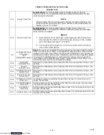
AL61 Heaters Failure
Alarm 61 is triggered by detection of improper amperage resulting from heater
activation or deactivation. Each phase of the power source is checked for proper
amperage.This alarm is a display alarm with no resulting failure action, and will
be reset by a proper amp draw of the heater.
AL62 Compressor Circuit
Failure
Alarm 62 is triggered by improper current draw increase (or decrease) resulting
from compressor turn on (or off). The compressor is expected to draw a mini-
mum of 2 amps; failure to do so will activate the alarm. This is a display alarm
with no associated failure action and will be reset by a proper amp draw of the
compressor.
AL63 Current Over Limit
Alarm 63 is triggered by the current limiting system. If the compressor is ON and
current limiting procedures cannot maintain a current level below the user se-
lected limit, the current limit alarm is activated. This alarm is a display alarm and
is inactivated by power cycling the unit, changing the current limit via the code
select Cd32, or if the current decreases below the activation level.
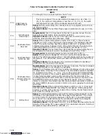
AL64 Discharge Tempera-
ture Over Limit
Alarm 64 is triggered if the discharge temperature sensed is outside the range of
--60
_
C (--76
_
F) to 175
_
C (347
_
F), or if the sensor is out of range. This is a dis-
play alarm and has no associated failure action.
AL65 Discharge Pressure
Transducer Failure
Alarm 65 is triggered if a compressor discharge transducer is out of range. This
is a display alarm and has no associated failure action.
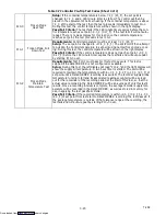
AL66 Suction Pressure
Transducer Failure
Alarm 66 is triggered if a suction pressure transducer is out of range. This is a
display alarm and has no associated failure action.
AL67 Humidity Sensor
Failure
Alarm 67 is triggered by a humidity sensor reading outside the valid range of 0%
to 100% relative humidity. If alarm AL67 is triggered when the dehumidification
mode is activated, then the dehumidification mode will be deactivated.
AL69 Suction Temperature
Sensor Failure
Alarm 69 is triggered by a suction temperature sensor reading outside the valid
range of --60
_
C (--76
_
F) to 150
_
C (302
_
F). This is a display alarm and has no
associated failure action.
Downloaded from
Summary of Contents for 69NT40-531 Series
Page 2: ...Downloaded from ManualsNet com search engine ...
Page 4: ...Downloaded from ManualsNet com search engine ...
Page 8: ...Downloaded from ManualsNet com search engine ...
Page 16: ...Downloaded from ManualsNet com search engine ...
Page 57: ...Downloaded from ManualsNet com search engine ...
Page 104: ...Downloaded from ManualsNet com search engine ...
Page 106: ...7 2 T 292 Figure 7 2 SCHEMATIC DIAGRAM Downloaded from ManualsNet com search engine ...

