T-292
4-8
4. The controller probe diagnostic logic determines that
a probe check is necessary based on the tempera-
ture values currently reported by the supply and re-
turn probes.
5. If the controller is programmed with the Demand De-
frost option (Future) and the option is set to “IN” the
unit will enter defrost if it has been in operation for
over 2.5 hours without reaching set point.
CONTROL TRANSFORMER
POWER TO
CONTROLLER
SIGNAL TO
CONTROLLER
ENERGIZED
DE--ENERGIZED
FOR FULL DIAGRAM AND
LEGEND, SEE SECTION 7
TD
T6
PA
PB
T6
PB
PA
USV
ESV
TU
TS
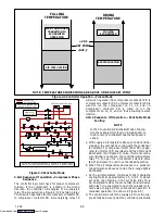
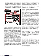
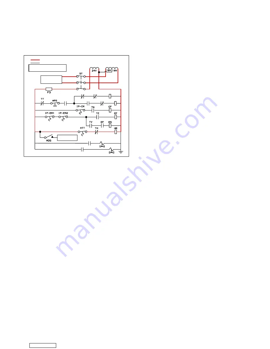
Figure 4-8 Defrost
Defrost may be initiated any time the defrost
temperature sensor reading falls below the controller
defrost termination thermostat set point. Defrost will
terminate when the defrost temperature sensor reading
rises above the defrost termination thermostat set point.
The defrost termination thermostat is not a physical
component. It is a controller setting that acts as a
thermostat, “closing” (allowing defrost) when the defrost
temperature sensor reading is below the set point and
“opening” (terminating or preventing defrost) when the
sensor temperature reading is above set point. When
the unit is operating in bulb mode (refer to paragraph
3.3.9), special settings may be applicable.
If the controller is programmed with the Lower DTT
setting option the defrost termination thermostat set
point may be configured to the default of 25.6
_
C (78
_
F)
or lowered to 18
_
C (64
_
F). When a request for defrost is
made by use of the manual defrost switch,
communications or probe check the unit will enter
defrost if the defrost temperature thermostat reading is
at or below the defrost termination thermostat setting.
Defrost will terminate with the defrost temperature
sensor reading rises above the defrost termination
thermostat setting. When a request for defrost is made
by the defrost intermale timer or by demand defrost, the
defrost temperature setting setting must be below 10_C
(50_F).
When the defrost mode is initiated the controller opens
contacts TD, TN and TE (or TV) to de-energize the
compressor, condenser fan and evaporator fans. The
COOL light is also de--energized.
The controller then closes TH to supply power to the
heaters. The defrost light is illuminated.
When the defrost temperature sensor reading rises to
the defrost termination thermostat setting, the de--icing
operation is terminated.
If defrost does not terminate correctly and temperature
reaches the set point of the heat termination thermostat
(HTT) the thermostat will open to de--energize the
heaters. If termination does not occur within 2.0 hours,
the controller will terminate defrost. An alarm will be
given of a possible DTS failure.
If probe check (controller function code CnF31) is
configured to special, the unit will proceed to the next
operation (snap freeze or terminate defrost). If the code
is configured to standard, the unit will perform a probe
check. The purpose of the probe check is to detect
malfunctions or drift in the sensed temperature that is
too small to be detected by the normal sensor out of
range tests. The system will run for eight minutes in this
condition. At the end of the eight minutes, probe alarms
will be set or cleared based on the conditions seen.
When the return air falls to 7
_
C (45
_
F), the controller
checks to ensure the defrost temperature sensor (DTS)
reading has dropped to 10
_
C or below. If it has not, a
DTS failure alarm is given and the defrost mode is
operated by the return temperature sensor (RTS).
If controller function code CnF33 is configured to snap
freeze, the controller will sequence to this operation.
The snap freeze consists of running the compressor
without the evaporator fans in operation for a period of
four minutes with the suction modulation valve fully
open. When the snap freeze is completed, defrost is
formally terminated.
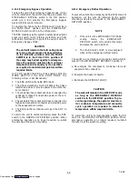
4.11 EMERGENCY OPERATION
Operation by the refrigeration controller may be
overridden by use of the EMERGENCY BYPASS or by
use of the EMERGENCY DEFROST switch. The
EMERGENCY BYPASS switch functions to bypass the
controller in the event of controller failure. Emergency
Bypass System can operate in one of two modes, FULL
COOL and FANS ONLY. The EMERGENCY DEFROST
switch functions to bypass the controller and place the
unit in the defrost mode.
Downloaded from
Summary of Contents for 69NT40-531 Series
Page 2: ...Downloaded from ManualsNet com search engine ...
Page 4: ...Downloaded from ManualsNet com search engine ...
Page 8: ...Downloaded from ManualsNet com search engine ...
Page 16: ...Downloaded from ManualsNet com search engine ...
Page 57: ...Downloaded from ManualsNet com search engine ...
Page 104: ...Downloaded from ManualsNet com search engine ...
Page 106: ...7 2 T 292 Figure 7 2 SCHEMATIC DIAGRAM Downloaded from ManualsNet com search engine ...

