T-292
4-9
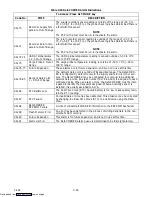
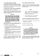
4.11.1 Emergency Bypass Operation
To place the unit in the emergency bypass mode, cut the
wire tie installed at the switch mounting and place the
EMERGENCY BYPASS switch in the ON position
which will in turn activate the Emergency Bypass
System (EBS) control module.
To operate the fans only the MODE switch must be in
the FANS ONLY position and the EMERGENCY
BYPASS Switch must be in the ON position.
The EBS module uses the system’s safety devices (high
pressure switch, motor internal protectors, and heat
termination thermostat) to protect the system while in
Emergency Bypass Mode.
CAUTION
The unit will remain in the full cooling mode
as long as the emergency bypass switch is
in the BYPASS position and the MODE
SWITCH is in the FULL COOL position. If
the cargo may be damaged by low tempera-
tures, the operator must monitor container
temperature and manually cycle operation
as required to maintain temperature within
required limits.
In the ON position the EBS will be enabled. With the
MODE SWITCH in the FULL COOL MODE. The
following will occur simultaneously:
1. The EBS switch will enable EBS input.
2. The phase detection circuit will detect the phase
rotation and close to provide power to the compres-
sor contactor.
3. The condenser fan contact will close to energize the
condenser contactor and provide power to the con-
denser fan motor.
4. The evaporator fan contact will close to energize the
high speed evaporator contactor and provide power
to the evaporator fan motor.
5. The EBS electronic module will open the SMV to
100%
To return the unit to normal operation, place the EBS
switch in the NORMAL OPERATION position. When
emergency operation is no longer required, re--install
the wire tie at the switch mounting.
4.11.2 Emergency Defrost Operation
To place the unit in the emergency defrost (ED) mode of
operation, cut the wire tie installed at the switch
mounting and place the switch in the EMERGENCY
DEFROST position.
NOTE
1. If the unit is in the EMERGENCY BYPASS
cooling
mode,
the
EMERGENCY
DEFROST switch will override this mode
and place the unit in defrost.
2. The IN--RANGE LIGHT is de--energized
when in the emergency defrost mode.
The switch is a normally open four pole switch which is
placed in the EMERGENCY DEFROST position to:
a. De--energize the compressor, condenser fan and
evaporator fan contactors.
b. Energize the heater contactor.
c. Illuminate the DEFROST LIGHT.
CAUTION
The unit will remain in the DEFROST mode
as long as the EMERGENCY DEFROST
switch is in the DEFROST position. To pre-
vent cargo damage, the operator must mon-
itor container temperature and manually
cycle operation as required to maintain
temperature within required limits.
To return the unit to normal operation, place the ED
switch in the NORMAL OPERATION position. When
emergency operation is no longer required, re--install
the wire tie at the switch mounting.
Downloaded from
Summary of Contents for 69NT40-531 Series
Page 2: ...Downloaded from ManualsNet com search engine ...
Page 4: ...Downloaded from ManualsNet com search engine ...
Page 8: ...Downloaded from ManualsNet com search engine ...
Page 16: ...Downloaded from ManualsNet com search engine ...
Page 57: ...Downloaded from ManualsNet com search engine ...
Page 104: ...Downloaded from ManualsNet com search engine ...
Page 106: ...7 2 T 292 Figure 7 2 SCHEMATIC DIAGRAM Downloaded from ManualsNet com search engine ...

