6-13
T-292
6.11 FILTER-DRIER
On units equipped with a water-cooled condenser, if the
sight glass appears to be flashing or bubbles are
constantly moving through the sight glass when the
suction modulation valve is fully open, the unit may have
a low refrigerant charge or the filter-drier could be
partially plugged.
a. To Check Filter-Drier
1. Test for a restricted or plugged filter-drier by feeling
the liquid line inlet and outlet connections of the drier
cartridge. If the outlet side feels cooler than the inlet
side, then the filter-drier should be changed.
2. Check the moisture-liquid indicator if the indicator
shows a high level of moisture, the filter-drier should
be replaced.
b. To Replace Filter-Drier
1. Pump down the unit (refer to paragraph 6.3.2). Eva-
cuate if unit is not equipped with service valves (Re-
fer to paragraph 6.4.4). Then replace filter-drier.
2. Evacuate the low side in accordance with paragraph
6.3.4.
3. After unit is in operation, inspect for moisture in sys-
tem and check charge.
6.12 EXPANSION VALVES
Three expansion valves are used, the evaporator
expansion valve (item 12, Figure 2-2), the quench
expansion valve (item 14, Figure 2-2) and the
economizer expansion valve (item 26, Figure 2-4). The
expansion valves are automatic devices which maintain
constant superheat of the refrigerant gas leaving at the
point of bulb attachment regardless of suction pressure.
The valve functions are:
1. Automatic control of the refrigerant flow to match the
load.
2. Prevention of liquid refrigerant entering the com-
pressor.
Unless the valve is defective, it seldom requires
maintenance other than periodic inspection to ensure
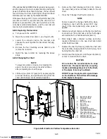
that the thermal bulb is tightly secured to the suction line
and wrapped with insulating compound. (See
Figure 6-12.)
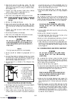
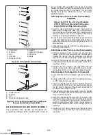
1
2
3
4
1. Suction Line
2. TXV Bulb Clamp
3. Nut and Bolt
4. TXV Bulb
Figure 6-12 Thermostatic Expansion Valve Bulb
6.12.1 Checking Superheat.
NOTE
Proper superheat measurement for the evapo-
rator expansion valve should be completed at
--18
_
C (0
_
F) container box temperature where
possible. If the economizer or quench valve is
suspect, it should be replaced.
a. Open the heater access panel (see Figure 2-1) to ex-
pose the evaporator expansion valve.
b. Attach a temperature sensor near the expansion
valve bulb and insulate. Make sure the suction line is
clean and that firm contact is made with the sensor.
c. Connect an accurate gauge to the service port direct-
ly upstream of the suction modulating valve.
d. Set the temperature set point to --18
_
C (0
_
F), and run
unit until conditions stabilize.
e. The readings may cycle from a high to a low reading.
Take readings of temperature and pressure every
three to five minutes for a total of 5or 6 readings
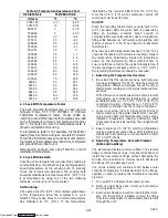
f. From the temperature/pressure chart (Table 6-8), de-
termine the saturation temperature corresponding to
the evaporator outlet test pressures at the suction
modulation valve.
g. Subtract the saturation temperatures determined in
step f. from the temperatures measured in step e..
The difference is the superheat of the suction gas.
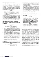
Determine the average superheat It should be 4.5 to
6.7
°
C (8 to 12
°
F)
Downloaded from
Summary of Contents for 69NT40-531 Series
Page 2: ...Downloaded from ManualsNet com search engine ...
Page 4: ...Downloaded from ManualsNet com search engine ...
Page 8: ...Downloaded from ManualsNet com search engine ...
Page 16: ...Downloaded from ManualsNet com search engine ...
Page 57: ...Downloaded from ManualsNet com search engine ...
Page 104: ...Downloaded from ManualsNet com search engine ...
Page 106: ...7 2 T 292 Figure 7 2 SCHEMATIC DIAGRAM Downloaded from ManualsNet com search engine ...

