6-14
T-292
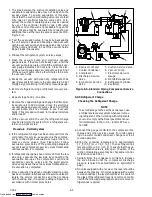
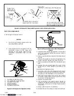
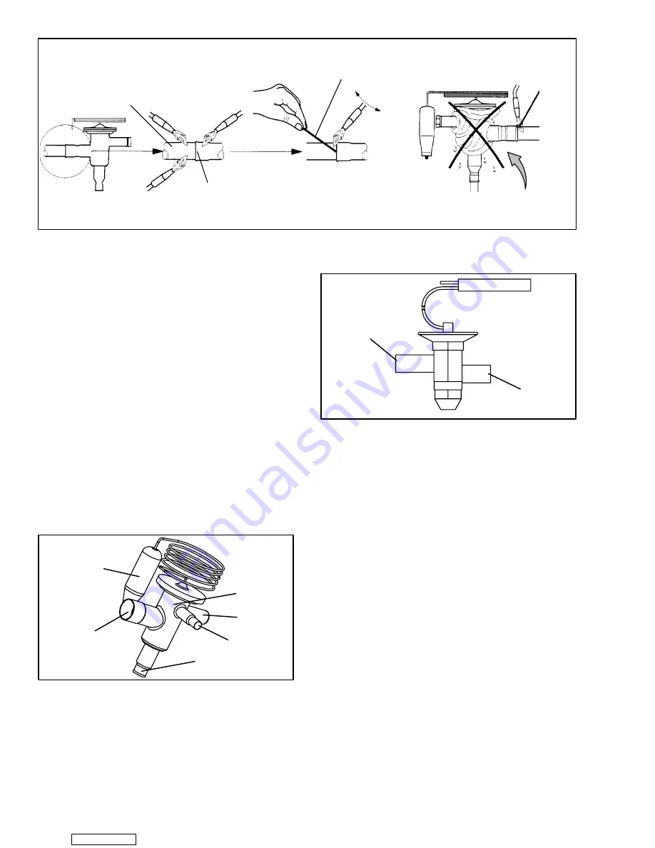
Copper Tube
(Apply heat for
10-15 seconds)
Bi-metallic Tube Connection
(Apply heat for 2-5 seconds)
Use of a wet cloth is not neces-
sary due to rapid heat dissipation
of the bi--metallic connections
Braze Rod
(’Sil-Phos” = 5.5% Silver, 6% Phosphorus)
Figure 6-13 Hermetic Thermostatic Expansion Valve Brazing Procedure
6.12.2 Valve Replacement
a. Removing the Expansion Valve
NOTES
1. The TXV’s are hermetic valves and do not
have adjustable superheat.
2. All connections on the evaporator TXV are
bi--metallic, copper on the inside and
stainless on the outside. When brazing,
bi--metallic connections heat up very
quickly.
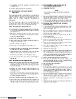
1
6
5
4
3
2
1. Evaporator Expansion Valve
2. Non-adjustable Superheat Stem
3. Equalizer Connection
4. Inlet Connection
5. Outlet Connection
6. Expansion Valve Bulb
Figure 6-14 Evaporator Expansion Valve
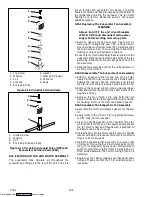
INLET
OUTLET
Figure 6-15 Quench & Economizer Expansion
Valves
1. Pump down the unit per paragraph 6.3.2. Evacuate if
unit is not equipped with service valves. Refer to
paragraph 6.4.4.
2. Remove cushion clamps located on the inlet and out-
let lines.
3. Unbraze the equalizer connection (if applicable), the
outlet connection and then the inlet connection.
4. Remove insulation (Presstite) from expansion valve
bulb.
5. Unstrap the bulb, located below the center of the
suction line (4 o’clock position), and remove the
valve.
b. Installing the Expansion Valve
1. Clean the suction line with sandpaper before instal-
ling bulb to ensure proper heat transfer. Apply ther-
mal grease to the indentation in the suction line.
2. Strap the thermal bulb to the suction line, making
sure bulb is placed firmly into the suction line. See
Figure 6-12 for bulb placement.
3. Insulate the thermal bulb.
4. The economizer and quench valves should be
wrapped in a soaked cloth for brazing. For the evap-
orator valve, see Figure 6-13. Braze inlet connection
to inlet line
5. Braze outlet connection to outlet line.
6. Reinstall the cushion clamps on inlet and outlet lines.
Downloaded from
Summary of Contents for 69NT40-531 Series
Page 2: ...Downloaded from ManualsNet com search engine ...
Page 4: ...Downloaded from ManualsNet com search engine ...
Page 8: ...Downloaded from ManualsNet com search engine ...
Page 16: ...Downloaded from ManualsNet com search engine ...
Page 57: ...Downloaded from ManualsNet com search engine ...
Page 104: ...Downloaded from ManualsNet com search engine ...
Page 106: ...7 2 T 292 Figure 7 2 SCHEMATIC DIAGRAM Downloaded from ManualsNet com search engine ...

