6-16
T-292
1
9
8
7
6
5
4
3
2
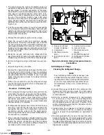
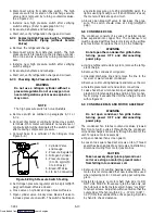
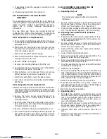
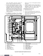
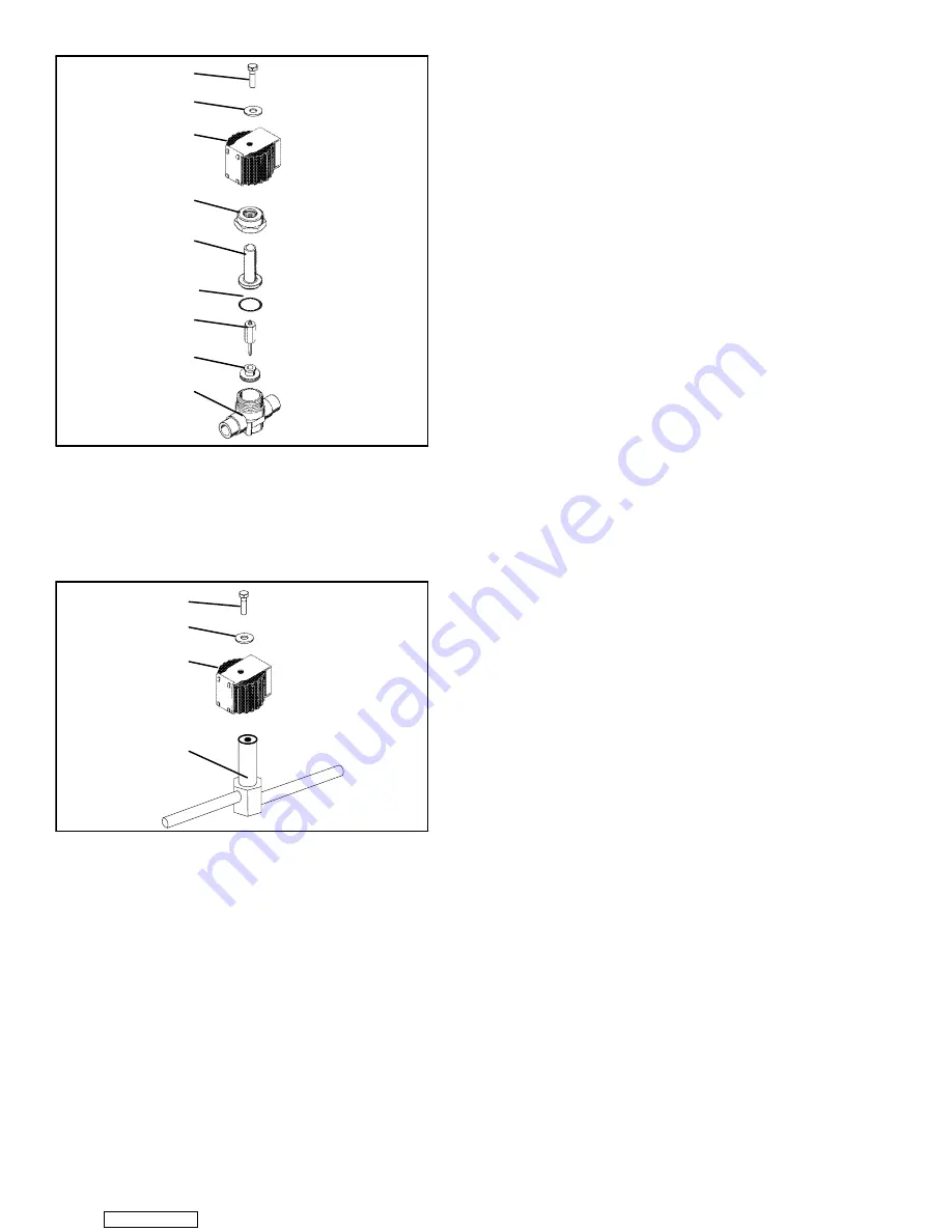
1. Top Screw
2. Washer
3. Coil
4. Locknut
5. Enclosing Tube
6. Gasket
7. Stem and Plunger
8. Seat Disc
9. Body
Figure 6-16. Unloader Solenoid Valve
1
2
3
4
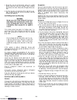
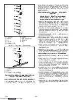
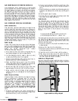
1. Slotted Screw
2. Washer
3. Coil
4. Enclosing Tube and Body
Figure 6-17. Oil Return Solenoid Valve (ORV) and
Economizer Solenoid Valve (ESV)
6.15 EVAPORATOR FAN AND MOTOR ASSEMBLY
The evaporator fans circulate air throughout the
container by pulling air in the top of the unit. The air is
forced through the evaporator coil where it is either
heated or cooled and then discharged out the bottom of
the refrigeration unit into the container. The fan motor
bearings are factory lubricated and do not require
additional grease.
6.15.1 Replacing The Evaporator Fan Assembly
WARNING
Always turn OFF the unit circuit breakers
(CB-1 & CB-2) and disconnect main power
supply before working on moving parts.
a. Remove upper access panel (see Figure 2-2) by
removing mounting bolts and T.I.R. locking device.
Reach inside of unit and remove the Ty-Rap securing
the wire harness loop. Then unplug the connector by
twisting to unlock and pulling to separate.
b. Loosen four 1/4-20 clamp bolts that are located on the
underside of the fan deck at the sides of the of the fan
assembly. Slide the loosened clamps back from the
fan assembly.
c. Slide the fan assembly out from the unit and place on
a sturdy work surface.
6.15.2 Disassemble The Evaporator Fan Assembly
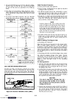
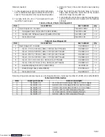
a. Attach a spanner wrench to the two 1/4-20 holes
located in the fan hub. Loosen the 5/8-18 shaft nut by
holding the spanner wrench stationary and turning
the 5/8-18 nut counter-clockwise (see Figure 6-18).
b. Remove the spanner wrench. Use a universal wheel
puller and remove the fan from the shaft. Remove the
washers and key.
c. Remove the four 1/4-20 x 3/4 long bolts that are
located under the fan that support the motor and sta-
tor housing. Remove the motor and plastic spacer.
6.15.3 Assemble The Evaporator Fan Assembly
a. Assemble the motor and plastic spacer onto the sta-
tor.
b. Apply loctite to the 1/4-20 x 3/4 long bolts and torque
to 0.81 mkg (70 inch-pounds).
c. Place one 5/8 flat washer on the shoulder of the fan
motor shaft. Insert the key in the keyway and lubricate
the fan motor shaft and threads with a graphite-oil
solution (such as Never-seez).
d. Install the fan onto the motor shaft. Place one 5/8 flat
washer with a 5/8-18 locknut onto the motor shaft and
torque to 40 foot-pounds.
e. Install the evaporator fan assembly in reverse order
of removal. Torque the four 1/4-20 clamp bolts to 0.81
mkg (70 inch-pounds) Apply power momentarily to
check for proper fan rotation (refer to paragraph 2.3).
If fan spins backward, then motor wiring or motor is
defective.
f. Replace access panel making sure that panel does
not leak. Make sure that the T.I.R. locking device is
lockwired.
Downloaded from
Summary of Contents for 69NT40-531 Series
Page 2: ...Downloaded from ManualsNet com search engine ...
Page 4: ...Downloaded from ManualsNet com search engine ...
Page 8: ...Downloaded from ManualsNet com search engine ...
Page 16: ...Downloaded from ManualsNet com search engine ...
Page 57: ...Downloaded from ManualsNet com search engine ...
Page 104: ...Downloaded from ManualsNet com search engine ...
Page 106: ...7 2 T 292 Figure 7 2 SCHEMATIC DIAGRAM Downloaded from ManualsNet com search engine ...

