6-17
T-292
1
2
3
4
5
6
5
7
8
9
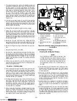
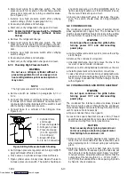
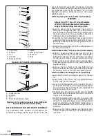
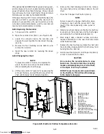
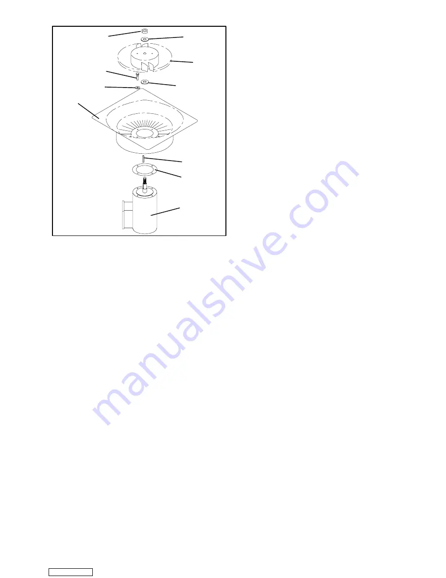
1. Stator
2. Flat washer, 1/4
3. Bolt, 1/4-20 x 3/4
4. Locknut, 5/8-18
5. Flat washer, 5/8
6. Impeller Fan
7. Key
8. Mylar Protector
9. Evaporator Motor
Figure 6-18. Evaporator Fan Assembly
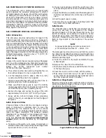
6.16 EVAPORATOR FAN MOTOR CAPACITORS
The evaporator fan motors are of the permanent-split
capacitor type. The motor is equipped with one
capacitor used in the high speed circuit and another
capacitor used for the low speed circuit.
6.16.1 When To Check For A Defective Capacitor
a. Fan motor will not change speed. For example: in the
conventional perishable mode, the motors should run
in high speed. In the economy perishable mode they
should switch speeds and in the frozen mode, the mo-
tors should run in low speed.
NOTE
The evaporator fan motors will always start in
high speed.
b. Motor running in wrong direction (after checking for
correct wiring application).
c. Motor will not start, and IP-EM’s are not open.
6.16.2 Removing The Capacitor
WARNING
Make sure power to the unit is OFF and
power plug disconnected before removing
capacitor(s).
The capacitors are located on the motor and above the
evaporator fan deck they may be removed by two
methods:
1
If container is empty
, open upper rear panel of the
unit. The capacitor may be serviced after discon-
necting power plug.
2
If container is full,
turn the unit power OFF and dis-
connect power plug. Remove the evaporator fan
motor access panel. (See Figure 2-1). For removal
of the evaporator fan assembly, refer to section 6.15.
WARNING
With power OFF discharge the capacitor
before disconnecting the circuit wiring.
6.16.3 Checking The Capacitor
If the capacitor is suspected of malfunction, you may
choose to simply replace it. Direct replacement requires
a capacitor of the same value. Two methods for
checking capacitor function are:
1. Volt-ohmmeter set on RX 10,000 ohms.
Connect ohmmeter leads across the capacitor
terminals and observe the meter needle. If the capacitor
is good, the needle will make a rapid swing toward zero
resistance and then gradually swing back toward a very
high resistance reading.
If the capacitor has failed open, the ohmmeter needle
will not move when the meter probes touch the
terminals. If the capacitor is shorted, the needle will
swing to zero resistance position and stay there.
2. Capacitor analyzer:
The function of the analyzer is to read the microfarad
value of a capacitor and to detect insulation breakdown
under load conditions. The important advantages of a
analyzer are its ability to locate capacitors that have
failed to hold their microfarad ratings, or those that are
breaking down internally during operation. It is also
useful in identifying capacitors when their microfarad
rating marks have become unreadable.
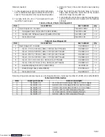
6.17 VALVE OVERRIDE CONTROLS
Controller function code Cd41 is a configurable code
that allows timed operation of the automatic valves for
troubleshooting. Three test sequences are provided.
The first, capacity mode (CAP), allows alignment of the
unloader and economizer solenoid valves in the
standard, unloaded and economized operating
configurations. The second, SMV % Setting (SM)
allows opening of the suction modulating valve to
various percentages and the third, Oil Valve Setting
(OIL) allows opening or closing of the oil return solenoid
valve.
A fourth selection is also provided to enter a time period
of up to three minutes, during which the override(s) are
active. If the timer is active, valve override selections will
take place immediately. If the timer is not active,
changes will not take place for a few seconds after the
timer is started. When the timer times out, override
function is automatically terminated and the valves
return to normal machinery control. To operate the
override, do the following:
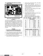
a. Press the CODE SELECT key then press an AR-
ROW key until Cd41 is displayed in the left window.
The right window will display a controller communica-
tions code.
b. Press the ENTER key. The left display will show a test
name alternating with the test setting or time remain-
ing. Use an ARROW key to scroll to the desired test.
Press the ENTER key and SELCt will appear in the
left display.
Downloaded from
Summary of Contents for 69NT40-531 Series
Page 2: ...Downloaded from ManualsNet com search engine ...
Page 4: ...Downloaded from ManualsNet com search engine ...
Page 8: ...Downloaded from ManualsNet com search engine ...
Page 16: ...Downloaded from ManualsNet com search engine ...
Page 57: ...Downloaded from ManualsNet com search engine ...
Page 104: ...Downloaded from ManualsNet com search engine ...
Page 106: ...7 2 T 292 Figure 7 2 SCHEMATIC DIAGRAM Downloaded from ManualsNet com search engine ...


