6-18
T-292
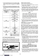
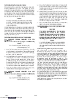
c. Use an ARROW key to scroll to the desired setting,
and then press the ENTER key. Selections available
for each of the tests are provided in the following
table.
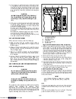
d. If the timer is not operating, follow the above proce-
dure to display the timer. Use an ARROW key to scroll
to the desired time interval and press ENTER to start
the timer.
e. The above described sequence may be repeated
during the timer cycle to change to another override.
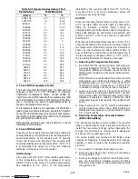
Right Display
Available Selections
CAP
(Capacity Mode)
AUtO
(Normal Control)
(
p
y
)
UnLd
(Unloader = Open
Economizer = Closed)
Std
(Unloader = closed
Economizer = closed)
ECOn
(Unloader = closed
Economizer = open)
SM
(SMV % Setting)
AUtO
(Normal Control)
3
4
6
12
25
50
100
OIL
(Oil Valve Setting)
AUto
(Normal Control)
(
g)
CLOSE
OPEn
LIV
(Liquid Valve Setting,
if
li bl )
AUto
(Normal Control)
( q
g,
if applicable)
CLOSE
OPEn
tIM
(Timer)
0 00
(0 minutes/0 Seconds)
In 30 second increments to
3 00
(3 minutes/ 0 seconds)
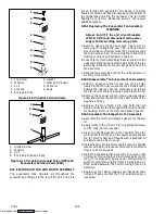
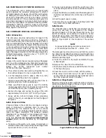
6.18 SUCTION MODULATION VALVE
On start up of the unit, the valve will reset to a known
open position. This is accomplished by assuming the
valve was fully open, driving it fully closed, resetting the
percentage open to zero, then opening to a known 10%
staging position.
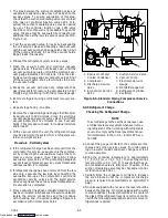
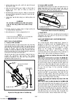
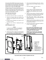
2-1/8 inch Nut
FROM COIL
FROM UNLOADER/QUENCH
TO COMPRESSOR
Figure 6-19 Suction Modulation Valve (SMV)
6.18.1 Precheck Procedure
a. Check unit for abnormal operation.
b. Check charge. If refrigerant is low repair as required
and again check operation.
c. If sufficient capacity cannot be maintained or unit is
tripping excessively on high pressure switch (HPS) in
high ambients, check coils and clean if required.
d. If capacity or control cannot be maintained turn unit
OFF, then back ON. This will reset the valve in the
event the controller lost communication with the
valve, and may correct the problem.
NOTE
Carefully listen to the valve. During reset, the
valve will make a ratcheting noise that may be
heard or felt as it is attempting to close. If this
can be heard or felt, it indicates that the control-
ler and drive module are attempting to close the
valve, and may serve as a quick indication that
the drive is in working order.
e. Operation of the valve may be checked using the con-
troller valve override program, function code Cd41.
Refer to paragraph 6.17 for valve override test in-
structions.
6.18.2 Checking The Stepper valve
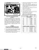
a. Checking with ohmmeter
Disconnect the four pin connector to the stepper SMV.
With a reliable digital ohmmeter, check the winding
resistance. In normal ambient, the valve should have 72
to 84 ohms measured on the red/green (a-b terminals)
and on the white/black (c-d terminals) leads. If an infinite
or zero reading occurs, check connections and replace
the motor.
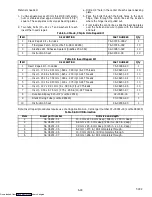
b. Checking with SMA-12 portable stepper drive tester
The SMA-12 portable stepper drive tester (Carrier
Transicold P/N 07-00375-00) is a battery operated
stepper drive which will open and close the SMV, which
allows a more thorough check of the operating
mechanism.
To check operation:
1. Stop the unit, disconnect the four pin connector from
the stepper module to the valve (see Figure 6-19)
and attach the SMA-12 stepper drive to the connec-
tor going to the valve.
2. Set the SMA-12 pulse per second (PPS) to one PPS
and either open or close valve. Each LED should
light sequentially until all four are lit. Any LED failing
to light indicates an open on that leg which indicates
a poor connection or an open coil. Repair or replace
as required to achieve proper operation.
CAUTION
The scroll compressor achieves low suc-
tion pressure very quickly. Do not operate
the compressor in a deep vacuum, internal
damage will result.
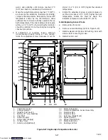
3. Restart unit, set the step rate to 200 PPS on SMA-12
for the valve, and close stepper valve while watching
the suction gauge. Within one minute the suction
pressure will go into a vacuum. This is an indication
that the valve is moving.
Downloaded from
Summary of Contents for 69NT40-531 Series
Page 2: ...Downloaded from ManualsNet com search engine ...
Page 4: ...Downloaded from ManualsNet com search engine ...
Page 8: ...Downloaded from ManualsNet com search engine ...
Page 16: ...Downloaded from ManualsNet com search engine ...
Page 57: ...Downloaded from ManualsNet com search engine ...
Page 104: ...Downloaded from ManualsNet com search engine ...
Page 106: ...7 2 T 292 Figure 7 2 SCHEMATIC DIAGRAM Downloaded from ManualsNet com search engine ...

