6-26
T-292
1
2
3
4
5
6
7
8
9
10
11
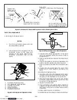
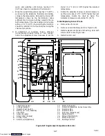
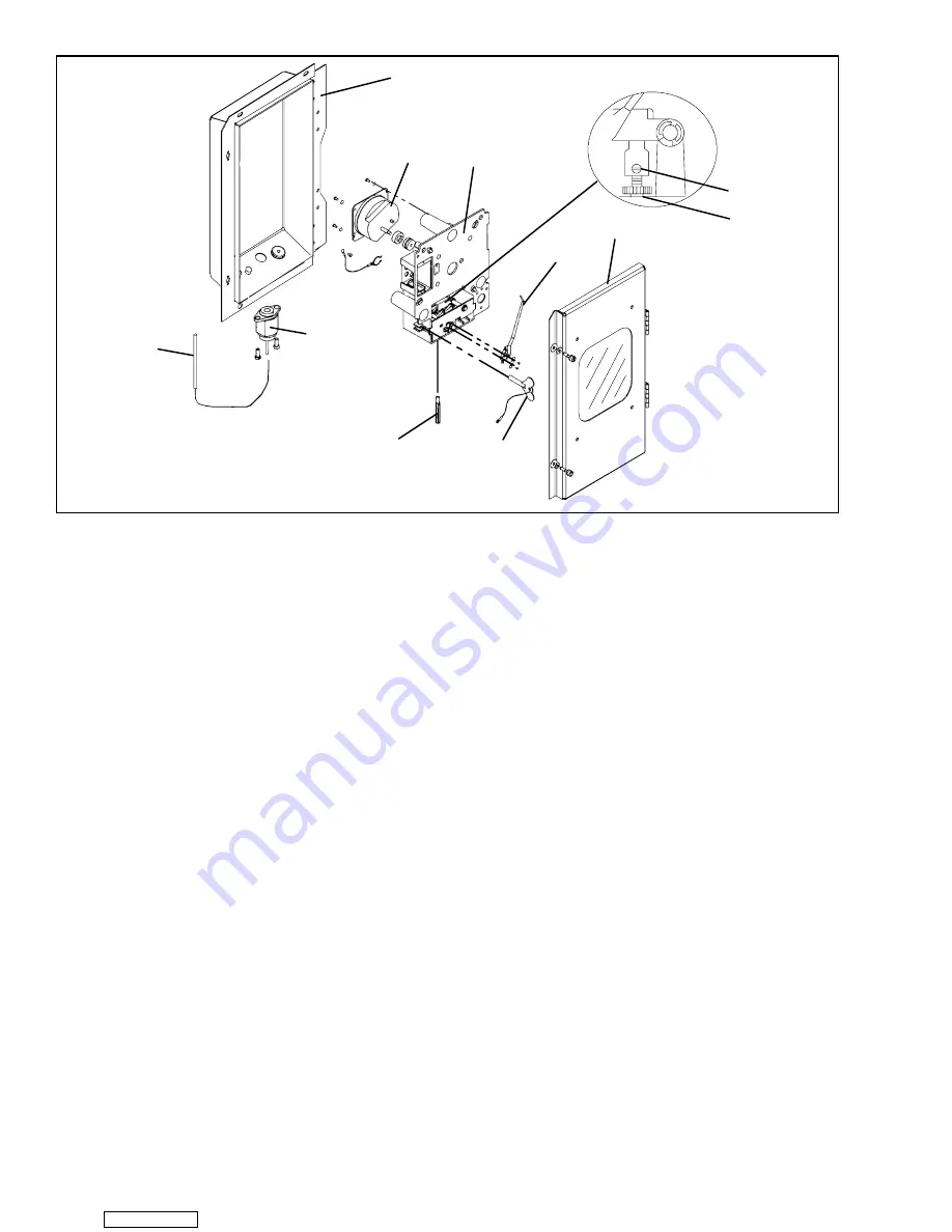
1. Mechanical Temperature
Recorder Bulb
2. Element
3. Recorder Box
4. 31 Day Clock
5. Mechanism and Platen Assembly
6. Set Screw
7. Pinion Shaft
8. Recorder Door
9. Stylus
10. Clock Winding Key
11. Push Rod
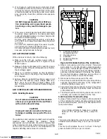
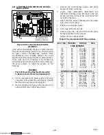
Figure 6-26. Partlow Mechanical Temperature Recorder
CAUTION
Recorder element capillary tubing may be
bent, but never sharper than 1/2” radius;
extra care should be taken when bending
adjacent to welds. The bulb should never
be bent, as this will affect calibration.
4 Push replacement bulb and capillary through the
unit.
5 Fill slots with silastic (RTV432, Dow Corning).
6 Attach bulb clamps tightly to sensor.
7 Connect element flange to recorder making sure hub
of flange faces out to fit into the hole in recorder box.
Install thermistor fitting if required.
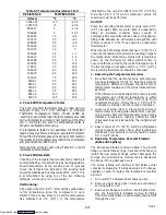
8. Rezero the recorder. (Refer to sections 6.23.a.
through 6.23.d.)
9. Install inlet air grille and upper panel. Start unit and
check recorder calibration.
6.24 SAGINOMIYA TEMPERATURE RECORDER
NOTE
Do not overtighten chart nut after replacing
chart.
6.24.1Battery Check
a. Open door and remove chart nut and platen.
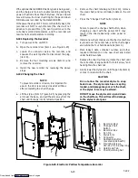
b. Push voltage indicator test switch (item 3,
Figure 6-27). Replace battery if voltage indicator
points to the red or white zone.
6.24.2Calibration
NOTES
1. One full turn with the adjustment screw
changes the indicated temperature by
approximately 5
°
C (9
°
F).
2. Overtightening of setscrew may change
set temperature.
3. Calibration should only be done when
sensor temperature is decreasing.
4. DO NOT move stylus by hand.
a. Install new chart on platen.
b. Place the recording thermometer sensing bulb in
0
°
C (32
°
F) ice-water bath. Ice-water bath is
prepared by filling an insulated container (of
sufficient size to completely immerse bulb) with ice
cubes or chipped ice, filling voids between ice with
Downloaded from
Summary of Contents for 69NT40-531 Series
Page 2: ...Downloaded from ManualsNet com search engine ...
Page 4: ...Downloaded from ManualsNet com search engine ...
Page 8: ...Downloaded from ManualsNet com search engine ...
Page 16: ...Downloaded from ManualsNet com search engine ...
Page 57: ...Downloaded from ManualsNet com search engine ...
Page 104: ...Downloaded from ManualsNet com search engine ...
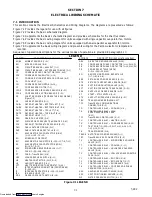
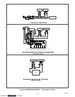
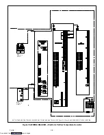
Page 106: ...7 2 T 292 Figure 7 2 SCHEMATIC DIAGRAM Downloaded from ManualsNet com search engine ...


