T-375
2–6
The engine requires all air to be removed the system in order to run at optimal performance. The fuel system
contains a fuel pump primer on the mechanical lift pump and an air bleed screw after the injection pump, if bleeding
air from the system is required.
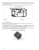
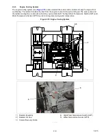
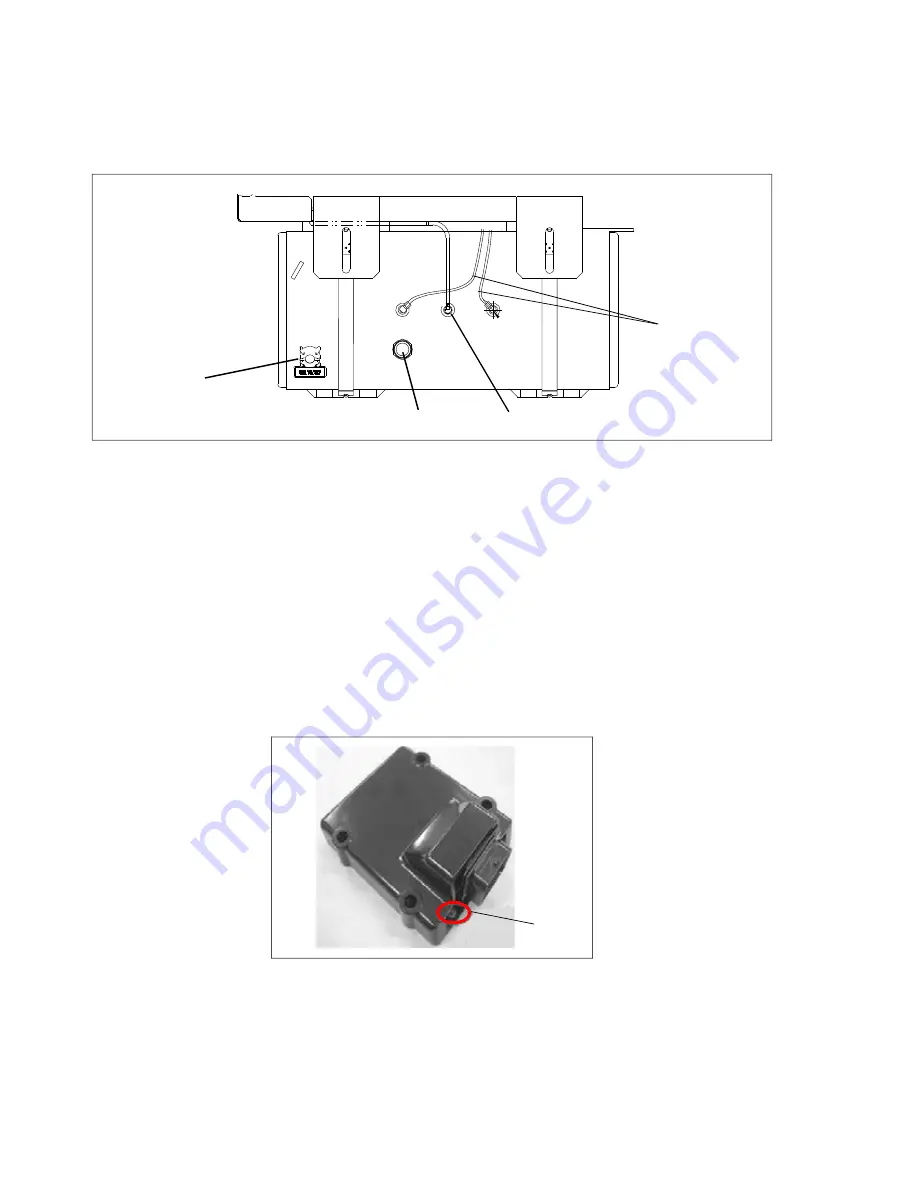
The engine fuel tank (see
) is available in 50 and 65 gallon capacity, with 50 gallon standard.
Figure 2.6 Fuel Tank
1) Cap
2) Gauge
3) Vent
4) Fuel Lines
- - - - -
2.4.2
Electronic Governor
The electronic governor controls the speed of the engine by using an Electronic Governor Module (EG), Fuel
Solenoid (FS) and an Engine Speed Sensor (ESS).
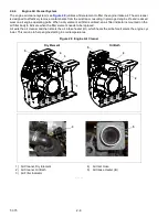
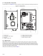
The EG (see
) is a solid state control module pre-programmed for 1800 RPM high speed and 1500 RPM
low speed operation. The EG receives an input signal from the ESS of the current RPM and compares this to a
preset value. The EG sends a correction signal to the FS to maintain the proper RPMs.
The EG is mounted in the control box and has an LED which may assist in diagnosing failures within the electronic
speed control system. See
for additional troubleshooting information.
Figure 2.7 Electronic Governor Module (EG)
1
2
3
4
LED
Summary of Contents for 69UG15
Page 2: ......
Page 4: ......
Page 12: ......
Page 32: ......
Page 40: ......
Page 58: ......
Page 60: ...T 375 6 2 Figure 6 2 Schematic for 12 VDC Control Circuit 12 VDC Control Circuit ...
Page 61: ...6 3 T 375 Figure 6 3 Schematic High Voltage Circuitry High Voltage Circuitry Receptacle Box ...
Page 62: ......
Page 65: ......


